Counterweight moving apparatus and crane

A mobile device and crane technology, applied in cranes and other directions, can solve the problems of low flexibility of counterweights and easy to limit the performance of construction machinery, and achieve the effects of increasing stable torque, reducing stable torque and enhancing flexibility.

Inactive Publication Date: 2015-09-09
BEIQI FOTON MOTOR CO LTD
View PDF10 Cites 2 Cited by
  • Summary
  • Abstract
  • Description
  • Claims
  • Application Information

AI Technical Summary

Problems solved by technology

[0004] The main purpose of the present invention is to provide a counterweight mobile device and a crane to solve the problem that the c

Method used


Image

  • Counterweight moving apparatus and crane
  • Counterweight moving apparatus and crane
  • Counterweight moving apparatus and crane

Examples


Embodiment 2

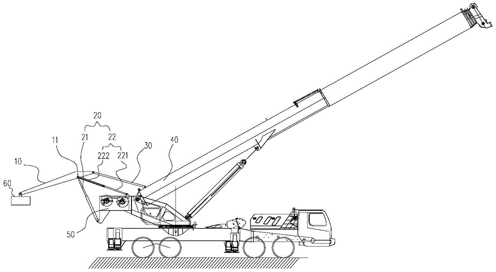
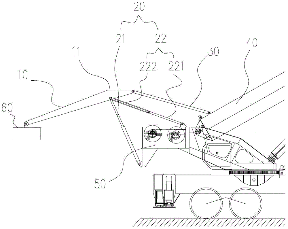
[0044] The main difference between the counterweight moving device of Embodiment 2 and Embodiment 1 is that the support rod 22 includes a first pull plate 221 and a second pull plate 222 that are movably connected, the second pull plate 222 has a slide groove 2221, and the first pull plate 221 has pin shaft 2211 that is slidably arranged in the chute 2221, and the free end of the second pull plate 222 forms the second installation end, and the free end of the first pull plate 221 is hinged with the middle part of swinging part 10 (not shown in the figure) out). The above structure realizes the expansion and contraction of the support rod 22 . The setting positions of the first pull plate 221 and the second pull plate 222 in this embodiment are opposite to those in the first embodiment, and their working process is similar to that in the first embodiment, and will not be repeated here.

Embodiment 3

[0045] The main difference between the counterweight moving device of Embodiment 3 and Embodiment 1 is that the support part 20 includes a second lifting cylinder and a third lifting cylinder, the first end of the second lifting cylinder is the third installation end, and the third lifting cylinder The first end of the lifting cylinder is the fourth installation end, the second end of the second lifting cylinder and the second end of the third lifting cylinder are both hinged with the middle of the swing part 10, or the second end of the second lifting cylinder It is hinged with the middle part of the swing part 10, and the second end of the third lifting cylinder is hinged with the middle part of the second lifting cylinder (not shown in the figure). In this embodiment, the above-mentioned first mounting end (ie, the first end of the second lifting cylinder) and the second mounting end (ie, the first end of the third lifting cylinder) are both hinged on the fixed structure of ...


PUM


Abstract

The invention provides a counterweight moving apparatus and a crane. The counterweight moving apparatus comprises a swing part (10), a first end of the swing part (10) comprises a counterweight connection part; a supporting part (20), wherein the supporting part (20) is hinged to a middle section of the swing part (10); and a driving part (30), which is connected to a second end of the swing part (10) and is capable of driving the swing part to swing around the supporting part (20) so as to make the swing part (10) to have an external swinging position and a recovery position. A technical scheme of the present invention can effectively solve the problems that flexibility of engineering machinery counterweight is not strong and engineering machinery performance is easily restricted in prior art.

Description

technical field [0001] The invention relates to the technical field of engineering machinery, in particular to a counterweight moving device and a crane. Background technique [0002] At present, the counterweight set on the construction machinery has a very important influence on the performance of the construction machinery. In the prior art, construction machinery usually adopts the form of fixedly connected counterweights, and the flexibility of fixedly connected counterweights is not strong, which limits the performance of construction machinery to a large extent. [0003] For example, the counterweight on the existing small-tonnage crane is in the form of fixed connection, and the counterweight is a key factor in determining the lifting capacity of the crane. Such as figure 1 As shown, in order to increase the lifting capacity of the crane to the greatest extent, the position of the counterweight 60' is usually set at the axle load limit of the rear axle 1' (that is,...

Claims


Application Information

Patent Timeline
IPC IPC(8): B66C23/76B66C23/62
CPCB66C23/76B66C23/62
Inventor 何晓鲁
Owner BEIQI FOTON MOTOR CO LTD
Why Eureka
Try Eureka