Eureka AIR delivers breakthrough ideas for toughest innovation challenges, trusted by R&D personnel around the world.

Saw gripping device for cutting machine

a cutting machine and sawing technology, applied in the field of cutting machines, can solve the problems of inapplicability to cutting saws having different thicknesses and drawbacks of conventional sawing gripping devices

Inactive Publication Date: 2009-03-12
MOBILETRON ELECTRONICS
View PDF13 Cites 5 Cited by
  • Summary
  • Abstract
  • Description
  • Claims
  • Application Information

AI Technical Summary

Benefits of technology

[0009]The primary objective of the present invention is to provide a saw gripping device for a cutting machine, which can prevent a cutting saw held thereby from accidental disengagement during reciprocating motion of the cutting machine.
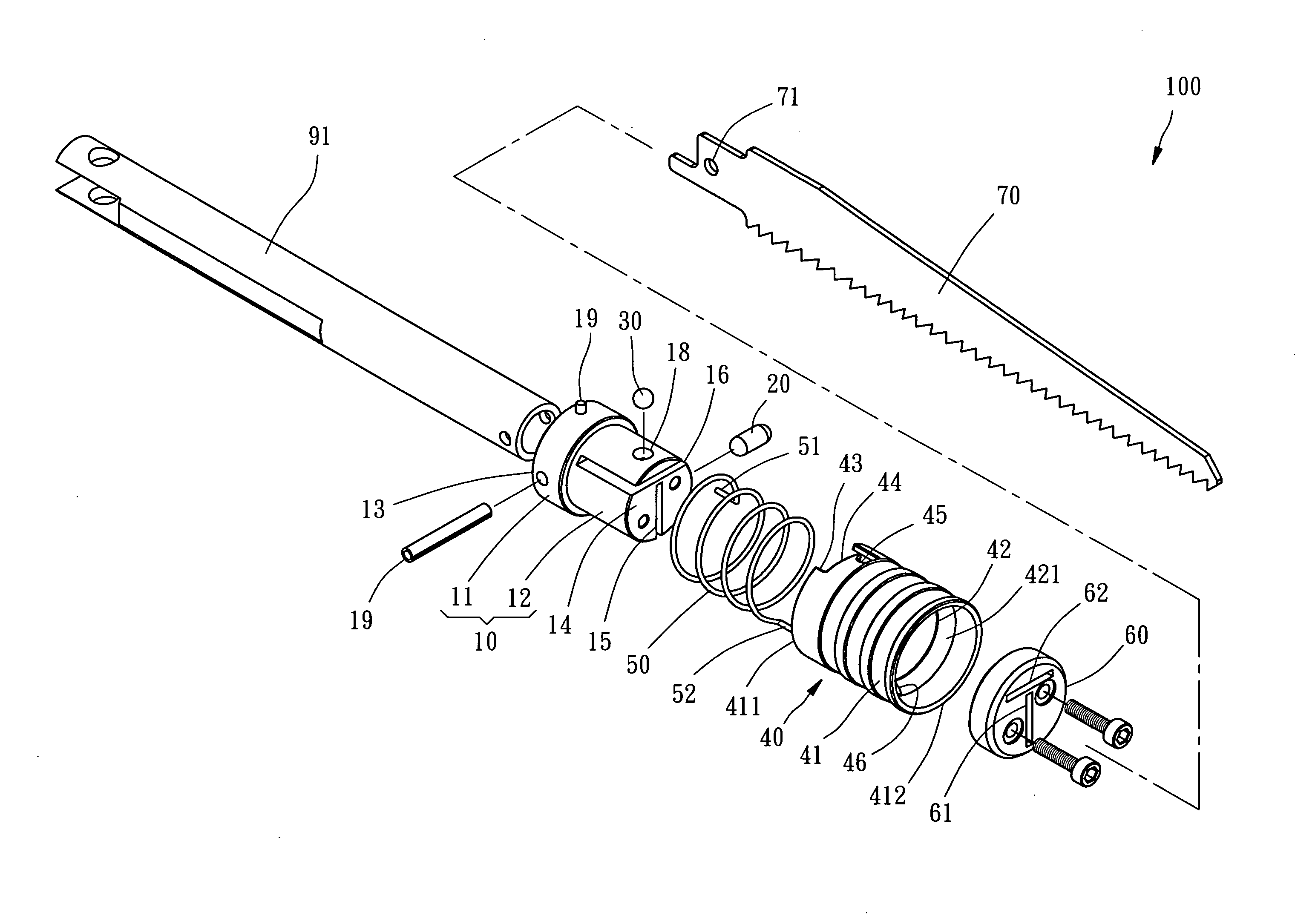
[0011]The foregoing objectives of the present invention are attained by the saw gripping device composed of a column-shaped main body, a tube-shaped control member, and a spring. The spring has two ends fixed to the main body and the control member respectively to be located therebetween, for applying axial impulse and torsion to the main body and the control member. The control member is sleeved onto the main body, having an inclined annular convexity formed on an internal sidewall thereof and a stopping portion extending slantwise from an end thereof toward the other end thereof. The main body includes a lug formed on an external sidewall thereof. The axial impulse and torsion applied to the control member can keep the inclined annular convexity lying against a stopper slidably inserted into the main body and keep the stopping portion lying against the lug.
[0012]In such a way that the stopping portion under the torsion of the spring lies against the lug, it prevents the control member from incorrect action incurred by an inertial force generated during the reciprocating motion of the cutting machine or by unexpected impact of an object. Where the stopping portion lies against the lug is variable subject to the thickness of the cutting saw and can still prevent the control member from incorrect action.

Problems solved by technology

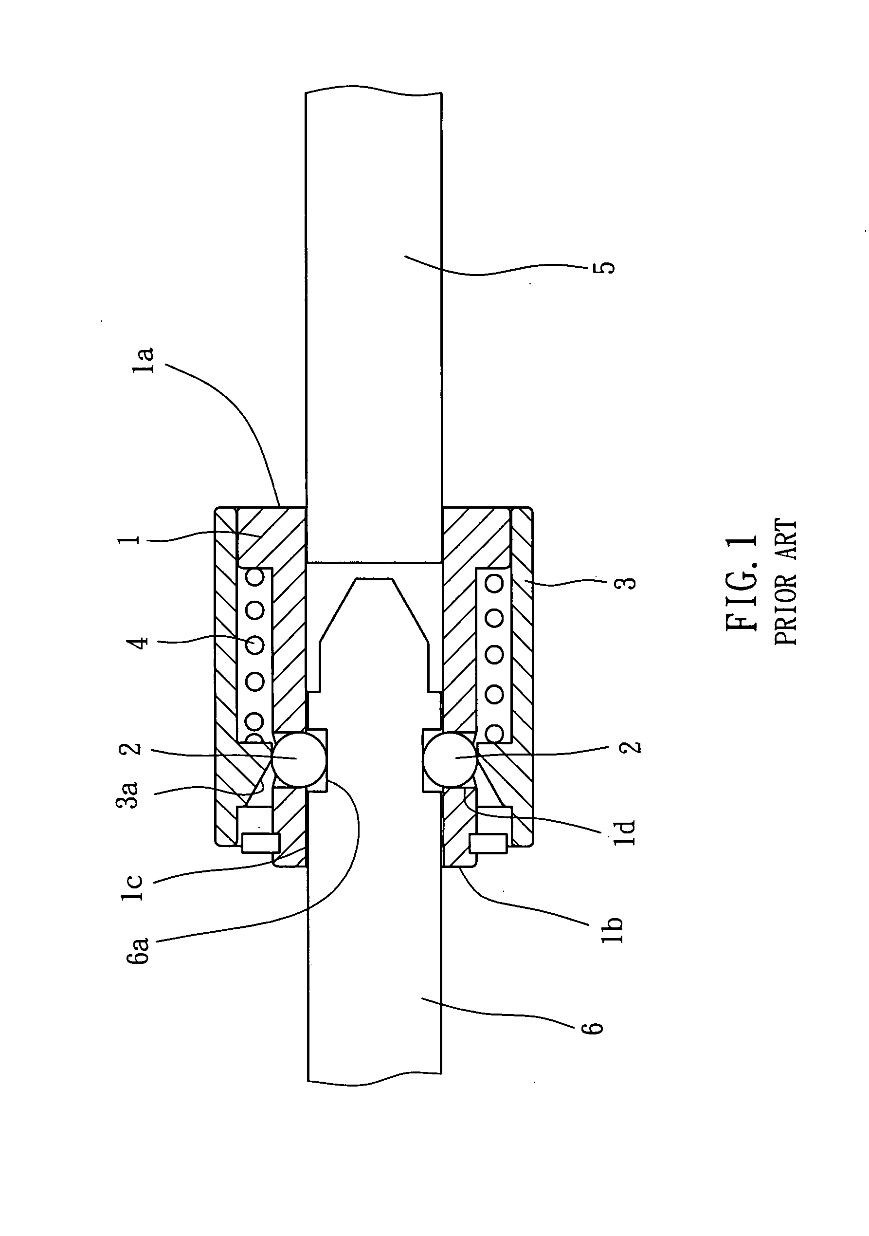
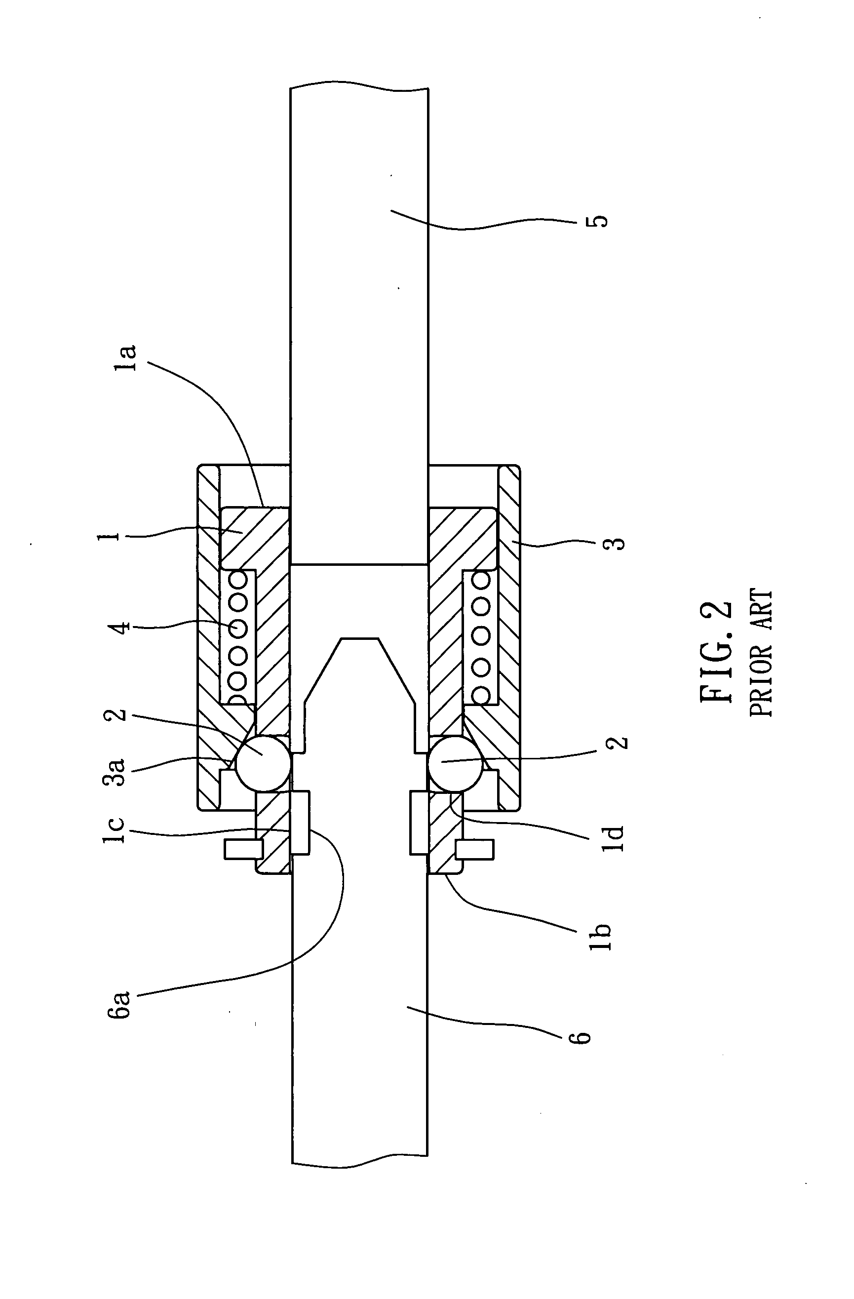
However, such conventional saw gripping device has some drawbacks.
Under the circumstances, it is very dangerous because the cutting saw 6 probably bounces to hurt the operator around the cutting machine after disengaging from the gripping device.
Besides, it may happen during the operation of the cutting machine or while the control member impinges a workpiece or other objects.
Although this improved saw gripping device improves the aforesaid drawback, the cutting saw is held bilaterally by two steel balls, such that it is inapplicable to cutting saws having different thickness.

Method used


Image

  • Saw gripping device for cutting machine
  • Saw gripping device for cutting machine
  • Saw gripping device for cutting machine

Examples


Embodiment Construction

[0028]Referring to FIGS. 3-5, a saw gripping device 100 for a cutting machine, constructed according to a preferred embodiment of the present invention, is composed of a main body 10, two stoppers 20 and 30, a control member 40, a spring 50, and a retaining member 60.

[0029]The main body 10 is column-shaped, having a head portion 11 and a body portion 12, which are axially connected in one piece. The head portion 11 has a larger external diameter than the body portion 12 does. The head portion 11 defines a first end 12 located at a free end thereof. The body portion 12 defines a second end 14 located at a free end thereof opposite to the first end 13. The first end 13 is adapted for fixed connection with an output shaft 91 of the cutting machine. The body portion 12 is provided with a first receiving slot 15, a second receiving slot 16, a first through hole 17, and a second through hole 18. The first and second receiving slots 15 and 16 are parallel to an imaginary center axis of the...


PUM

PropertyMeasurementUnit
Thicknessaaaaaaaaaa
Diameteraaaaaaaaaa
Distanceaaaaaaaaaa

Abstract

A saw gripping device for a cutting machine includes a main body having a lug formed on an external sidewall thereof; a control member slidably sleeved onto the main body and having an inclined annular convexity formed on an internal sidewall thereof and a stopping portion extending slantwise from an end thereof toward the other end thereof; and a spring having two ends fixed to the main body and the control member respectively to be located therebetween for keeping the inclined annular convexity lying against a stopper slidably inserted into the main body and to keep the stopping portion lying against the lug. In light of this, the control member can be prevented from incorrect action during the reciprocating motion of the cutting machine. In addition, where the stopping portion lies against the lug is variable subject to the thickness of the cutting saw.

Description

BACKGROUND OF THE INVENTION[0001]1. Field of the Invention[0002]The present invention relates generally to cutting machines, and more particularly, to a saw gripping device for a cutting machine.[0003]2. Description of the Related Art[0004]A common cutting machine includes an output shaft, which can be moved in linear reciprocating manner. The output shaft has a free end connected with a saw gripping device provided for holding a cutting saw. The cutting saw can be synchronically driven by the cutting saw for linear reciprocating motion to cut a workpiece.[0005]Referring to FIGS. 1 and 2, a conventional saw gripping device is composed of a main part 1, two steel balls 2, a control member 3, and a spring 4. The main part 1 is a column, having a first end 1a located an end thereof for connection with an output shaft 5 of a cutting machine, and a second end 1b located at an opposite end thereof. The main part 1 includes a receiving tunnel 1c and two through holes 1d. The receiving tunn...

Claims


Application Information

Patent Timeline
IPC IPC(8): B23D51/08
CPCY10T279/17803B23D51/08
Inventor TENG, CHENG-ICHEN, JIN-HUNG
Owner MOBILETRON ELECTRONICS
Why Eureka
Eureka Blog
Learn More