
Electrical operating device and method for recognizing malfunctions

a technology of operating device and malfunction, applied in the direction of fault response, digital circuit testing, instruments, etc., can solve the problems of seu effect, liable to faulty functions, inconvenient operation,

Pending Publication Date: 2022-08-04
SIEMENS AG
View PDF0 Cites 0 Cited by
  • Summary
  • Abstract
  • Description
  • Claims
  • Application Information

AI Technical Summary

Benefits of technology

The invention provides an economical operating device that can securely avoid errors in the control of an energy grid caused by ionizing radiation on semiconductor components. The device can be easily integrated into existing or future devices without the need for hardware changes, resulting in cost savings for manufacturers and energy grid operators. Additionally, the device has an analog / digital converter that can convert analog electrical measured values into digital measured values at a predefined sampling rate. The invention also provides a method for recognizing malfunctions in the operating device to avoid errors in energy grid control.

Problems solved by technology

It manifests, for example, as a bit-flip (a change in the state of one bit) in memory components or registers, which can lead to an incorrect function of the component concerned.
FPGAs based on static random access memory (SRAM) are often used; these are economical, but are subject to the SEU effect, and therefore liable to faulty functions.
Analog measured values for voltages and currents are, in particular, to be considered as particularly critical, since after the digitization of the analog measured variables, a single corrupt digital measured value can lead to an incorrect decision in the device.
In safety technology this could, for example, lead to an incorrect triggering of the protection device, and thus to switching off of a grid section.
A high financial cost could ensue.
This type of construction is comparatively complex and expensive; it also entails an increased space requirement.
A faulty function can occur within this period leading, for example, to incorrect switching operations and to the associated damage.
The fact that flash-based FPGAs are significantly more expensive than SRAM-based FPGAs is disadvantageous.

Method used


Image

  • Electrical operating device and method for recognizing malfunctions

Examples


Embodiment Construction

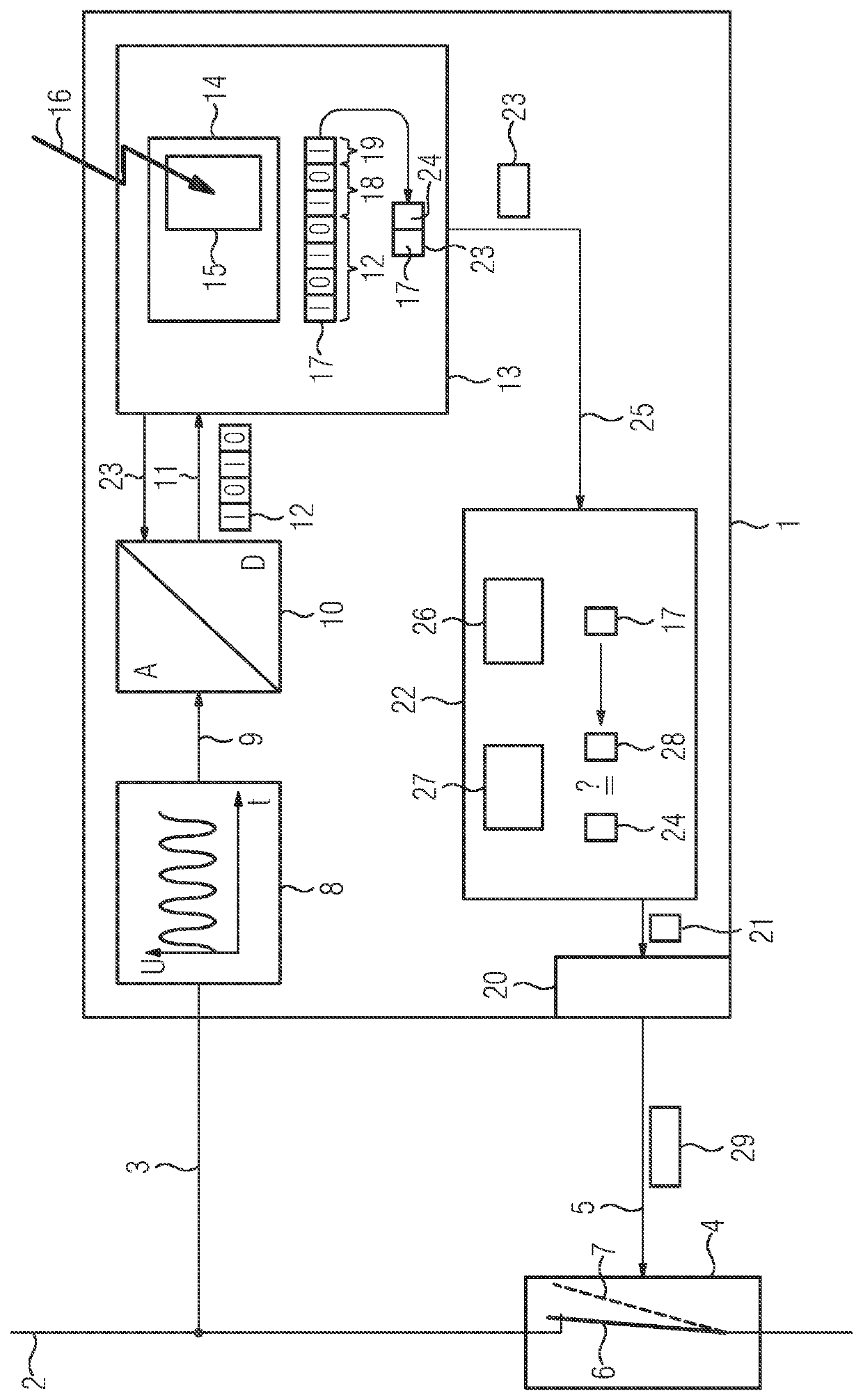
[0043]An electrical line 2 of an energy transmission grid of the high-voltage level is connected (possibly via a non-illustrated measuring transducer) by means of the line 3 to an electrical operating means 1 that is designed as a protection device. A measured value processing chain is illustrated in the protection device 1.

[0044]Measuring equipment 8 for an electrical measured variable is designed to determine the time profile of a voltage U. Analog measured values are output via an analog connection 9, which in this case is an instantaneous voltage value. The instantaneous voltage value is converted in an analog / digital converter 10 at a predefined sampling rate of, for example, 8 kHz into a bit sequence (e.g. “1010”), which indicates a digital measured value 12.

[0045]This digital measured value 12 is, for example, retrieved by preprocessing equipment 13 for digital measured values 12. The preprocessing equipment here comprises an integrated circuit 14 and an electronic memory com...


PUM


Abstract

An electrical operating device includes measuring equipment for an electrical measured variable, and preprocessing equipment for digital measured values. The preprocessing equipment has an integrated circuit and an electronic memory component for configuring a logic circuit. A processor evaluates preprocessed measurement data and, on the basis of the evaluation, transmits data telegrams to other electrical operating devices. The preprocessing equipment calculates a respective checksum for a digital measured value, and the processor recognizes a malfunction from the measured value and the checksum of the measured value, and suppresses the evaluation and / or the transmission of the data telegrams in the event of a malfunction. There is also described a method for recognizing malfunctions.

Description

CROSS-REFERENCE TO RELATED APPLICATION[0001]This application claims the priority, under 35 U.S.C. § 119, of European Patent Application EP 21154309.5, filed Jan. 29, 2021; the prior application is herewith incorporated by reference in its entirety.FIELD AND BACKGROUND OF THE INVENTION[0002]The invention relates to an electrical operating device, or operating means, with measuring equipment for an electrical measured variable and preprocessing equipment for digital measured values. The preprocessing equipment comprises an integrated circuit and an electronic memory component for the configuration of a logic circuit. A processor is designed to evaluate the preprocessed measurement data and, on the basis of the evaluation, to transmit data telegrams to other electrical operating device. There is also described a method for recognizing malfunctions with the following method steps: measuring an electrical measured variable with measuring equipment and preprocessing digital measured value...

Claims


Application Information

Patent Timeline
IPC IPC(8): G01R31/317H02H1/00
CPCG01R31/31708H02H1/0092G06F11/1004G06F11/0796G06F11/0736G01R31/002G01R31/31816H02H3/08H02H3/20H02H3/28H02H3/05H02H1/04
Inventor PERSDORF, DENNISMIESKE, FRANK
Owner SIEMENS AG
Learn More