Mass measurement device

a mass measurement and measuring device technology, applied in the direction of instruments, manufacturing tools, transportation and packaging, etc., can solve the problems of affecting the sensing action of the sensor, the movement of the movable part used in the sensing action is unlikely to be hindered, and the suction channel pulsates, so as to reduce the measurement error caused by the air suctioning action

Active Publication Date: 2017-10-05
ISHIDA CO LTD
View PDF4 Cites 0 Cited by
  • Summary
  • Abstract
  • Description
  • Claims
  • Application Information

AI Technical Summary

Benefits of technology

[0005]An object of certain implementations of the present invention is to reduce measurement error caused by an air-suctioning action in a mass measurement device.
[0032]Provided that the mass measurement device according to the present invention is used, measurement error caused by the air-suctioning action is reduced.

Problems solved by technology

However, when the suction channel is constituted of a flexible hose, it is likely that the suction channel pulsates during the air-suctioning action, or move the instant that the air-suctioning action begins or ends.
Such suction channel movement could have an adverse effect on the sensing action of a sensor that measures the mass of an article.
As a result, movement of the movable part used in the sensing action is unlikely to be hindered.
As a result, the movement of the movable part used in the sensing action is unlikely to be hindered.

Method used


Image

  • Mass measurement device
  • Mass measurement device
  • Mass measurement device

Examples


first embodiment

[0050](1) Boxing Apparatus

[0051](1-1) Configuration and Action of Boxing Apparatus

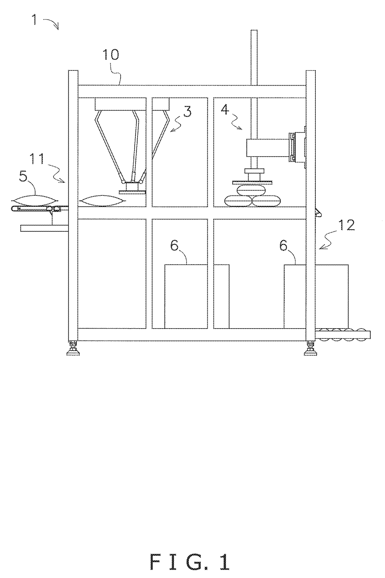
[0052]FIG. 1 shows an external view of a boxing apparatus 1 equipped with a mass measurement device according to a first embodiment of the present invention. This boxing apparatus 1 is used for filling a packing box 6 with multiple articles 5.

[0053]A frame 10 of the boxing apparatus 1 is provided with an entry area 11 for receiving articles 5, and an exit area 12 for ejecting a packing box 6 that has finished being filled with multiple articles 5. Furthermore, a parallel link robot 3 and a boxing robot 4 are installed to the frame 10.

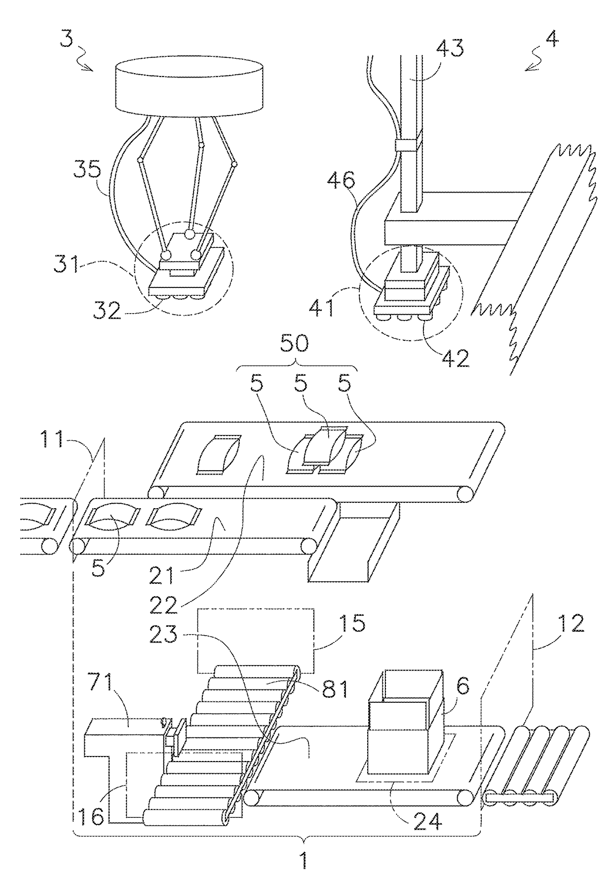
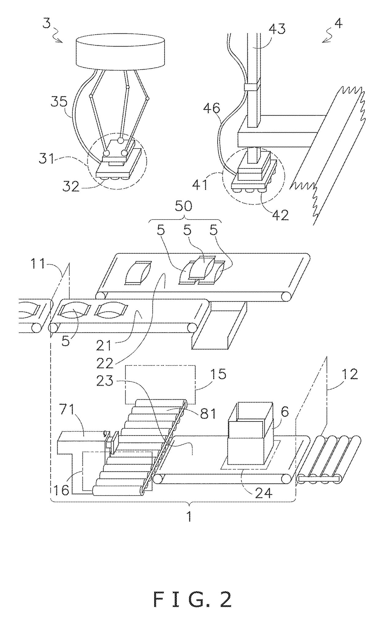
[0054]FIG. 2 shows the internal configuration of the boxing apparatus 1.

[0055]Articles 5 are inserted through the entry area 11. The articles 5 are conveyed a predetermined distance by a first conveyor 21, and are then raised up by the parallel link robot 3. Tubular vacuum-retaining tools 32 are provided to a head 31 of the parallel link robot 3, and the head 31 can hold a...

second embodiment

[0091](1) Boxing Apparatus

[0092]FIG. 9 shows the internal configuration of a boxing apparatus 1 equipped with a mass measurement device according to a second embodiment of the present invention. The second embodiment has the same elements as the first embodiment aside from the structure of the head 41a of the boxing robot 4 being different from the structure of the head 41 of the first embodiment. Specifically, in the second embodiment, air suctioned through the vacuum-retaining tools 42 of the head 41a of the boxing robot 4 first comes out of the head 41a to pass through the hose 46, then returns to the head 41a, and thereafter passes through the internal space in the mast 43 and heads toward the vacuum pump VP (FIG. 3).

[0093](2) Configuration of Mass Measurement Device

[0094]The mass measurement device according to the second embodiment of the present invention is also constituted of a head 41a of the boxing robot 4, a hose 46, a vacuum pump VP, a detection unit DT, a computation u...

third embodiment

[0125]FIG. 15 shows a head 41d of a mass measurement device according to a third embodiment of the present invention. In this drawing, the x-axis, y-axis, and z-axis directions are the same as those in FIG. 11, and it should be noted that the z-axis direction is the vertical direction. In the head 41d of the third embodiment, in place of a pair of hoses 46 of the head 41a (FIG. 11) according to the second embodiment, two sets each of which includes a base-part-side rigid pipe 461, a hose 462, and a movable-part-side rigid pipe 463 are employed. The head 41d according to the third embodiment is otherwise the same as the head 41a according to the second embodiment.

[0126]The base-part-side rigid pipes 461 and the movable-part-side rigid pipes 463 are composed of a metal or another rigid material, and thus do not pulsate during suction action. The hose 462 links the base-part-side rigid pipe 461 and the movable-part-side rigid pipe 463.

[0127]The sensitivity direction S of the sensor is ...


PUM

PropertyMeasurementUnit
mass measurementaaaaaaaaaa
forceaaaaaaaaaa
massaaaaaaaaaa

Abstract

A mass measurement device comprises a force sensor, a hose, a base part, an article-holding part, and a computation unit. The force sensor has a fixed end and a free end, and outputs a sensing signal in accordance with the magnitude of a force in a sensitivity direction. The hose is configured to pass suctioned air through it. The fixed end is fixed to the base part. The article-holding part is fixed to the free end, one end of the hose is connected to the article-holding part, and the article-holding part holds an article by air suction. The computation unit computes the mass of the article based on the sensing signal.

Description

PRIORITY[0001]This is a National Stage Application under 35 U.S.C. §365 of International Application PCT / JP2015 / 076378, with an international filing date of Sep. 17, 2015, which claims priority to Japanese Patent Application No. 2014-191638 filed on Sep. 19, 2014. The entire disclosures of International Application PCT / JP2015 / 076378 and Japanese Patent Application No. 2014-191638 are hereby incorporated herein by reference.TECHNICAL FIELD[0002]Certain implementations of the present invention relate to a mass measurement device.BACKGROUND ART[0003]Various devices have been envisioned which measure the mass of an article by using an article-holding part that vacuum-retains the article by suctioning air. A mass measurement device may use an article-holding part referred to as a “robot hand” that suctions air. The weight of the article held by the robot hand is computed from an output signal of a sensor installed in proximity to the robot hand.SUMMARY[0004]To suction air, for example, a...

Claims


Application Information

Patent Timeline
Patent Type & Authority Applications(United States)
IPC IPC(8): G01G3/142G01G19/18B65B61/28B25J9/00B65G47/90B65G47/91G01L1/22B25J15/06
CPCG01G3/142G01L1/225G01L1/2287G01G19/18B65B61/28B25J9/003B65G47/902B65G47/91B25J15/0616G01G23/00G01G23/01
Inventor SUZUKI, AKIHITONAKATANI, MAKOTOMINAMINO, SHIZUO
Owner ISHIDA CO LTD
Why Eureka
Try Eureka