Mass flow meter and mass flow controller

a flow meter and controller technology, applied in the field of flow rate sensors, can solve the problems of varying the error of the measured flow rate resulting from the change of the primary side pressure, and the measurement accuracy of the flow rate drops, so as to improve the measurement accuracy of the flow rate of the mass flow meter and reduce the measurement error of the flow rate

Active Publication Date: 2013-01-22
HORIBA STEC CO LTD
View PDF29 Cites 53 Cited by
  • Summary
  • Abstract
  • Description
  • Claims
  • Application Information

AI Technical Summary

Benefits of technology

[0016]In accordance with this invention having the above arrangement, since it is possible not only to decrease a measurement error of the flow rate resulting from a change of the primary side pressure as much as possible but also to correct the measured flow rate with the gas coefficient determined for each sample gas, the measurement accuracy of the flow rate of the mass flow meter can be improved.

Problems solved by technology

However, the above-mentioned mass flow meter has a problem that the measurement accuracy of the flow rate drops because of the error in the measured flow rate in a case where the gas supply pressure (primary side pressure) is changed (for example, 100 kPa) in the main flow channel where the mass flow meter is arranged.
In addition, there is a problem that the error of the measured flow rate resulting from the change of the primary side pressure varies depending on a kind of the sample gas.Patent document 1: Japan patent laid-open number 7-271447

Method used


Image

  • Mass flow meter and mass flow controller
  • Mass flow meter and mass flow controller
  • Mass flow meter and mass flow controller

Examples


first embodiment

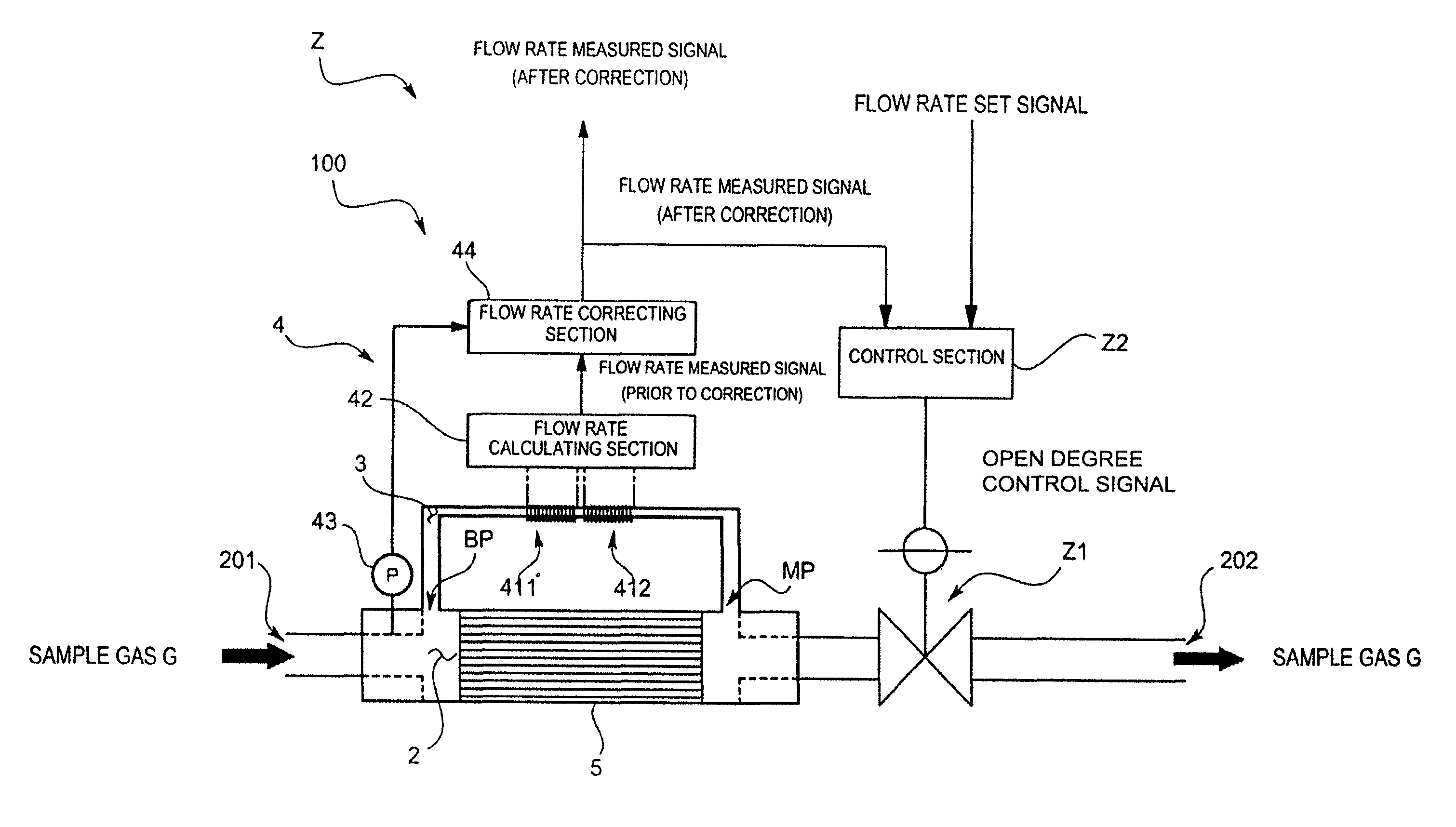
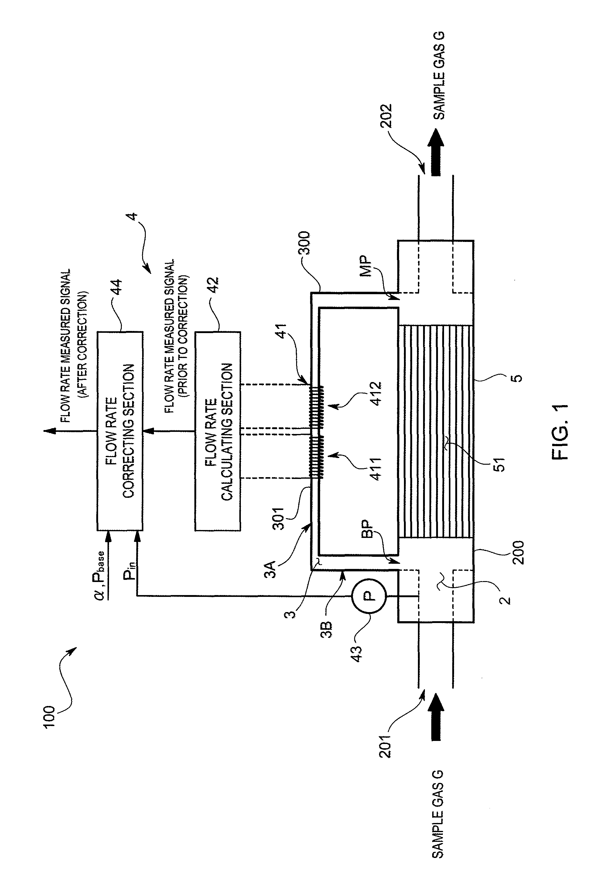
[0028]A first embodiment of a mass flow meter 100 in accordance with this invention will be explained with reference to drawings. FIG. 1 is a pattern configuration diagram showing the mass flow meter 100 in accordance with this embodiment.

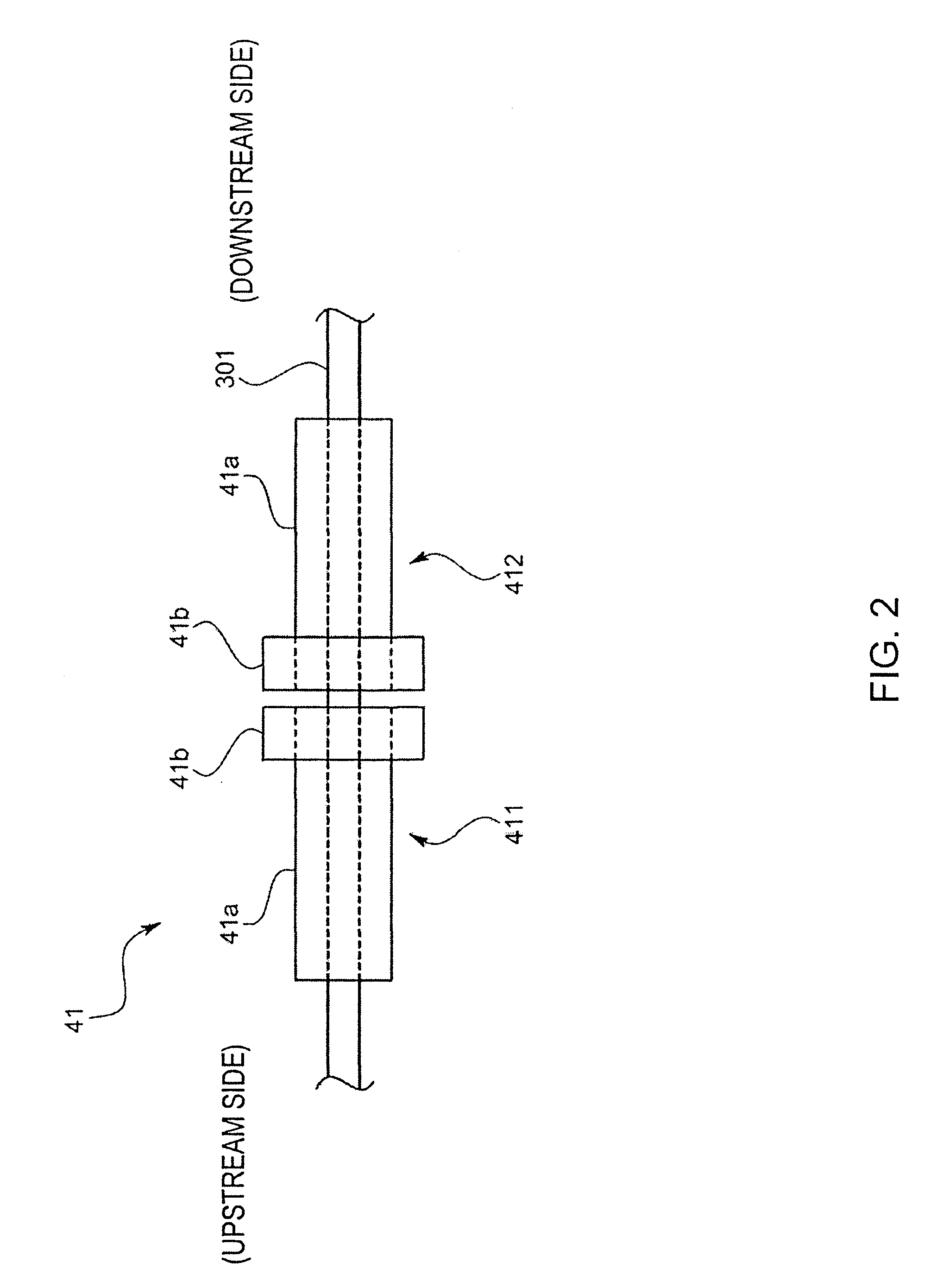
[0029]The mass flow meter 100 in accordance with this embodiment is a thermal mass flow meter and comprises a main flow channel 2 where a sample gas G that is a fluid (for example, a gas for processing a semiconductor such as SF6) flows, a sensor flow channel 3 that bifurcates from the main flow channel 2 and divides the sample gas G so as to detect a flow rate Qraw of the sample gas G, a flow rate detecting mechanism 4 that detects the flow rate Qraw of the sample gas G, and a laminar flow element 5 that is arranged between a bifurcating point BP and a meeting point MP of the sensor flow channel 3 in the main flow channel 2 and that has multiple internal flow channels 51.

[0030]Each section 2˜5 will be explained.

[0031]The main flow channel 2 is for...

second embodiment

[0053]Next, a second embodiment of the mass flow meter 100 in accordance with this invention will be explained. The mass flow meter 100 of this embodiment further comprises a relational expression data storing section D1 as shown in FIG. 5, and a function of the flow rate correcting section 44 differs from that of the first embodiment.

[0054]The relational expression data storing section D1 stores a relational expression data showing a relational expression of a coefficient a (a gradient a) and a coefficient b (an intercept b) to the gas physicality value in the following approximate expression (2) wherein the error [%] from the flow rate at the reference pressure Pbase is approximated by a predetermined function (a linear expression in this embodiment). The relational expression is input by a user in advance by means of an input device.

[Expression 4]

Error[%]=a×Qraw+b  (2)

where, each of the gradient a and the intercept b depends on a kind of the sample gas G as far as a specification...

other modified embodiment

[0073]The present claimed invention is not limited to the above-mentioned embodiment. In the following explanation, the same code will be given to the component corresponding to the above-mentioned embodiment.

[0074]For example, the approximate expression of the error [%] is not limited to a linear expression and may be a polynomial (quadratic and over) expression. A function of the gradient a and the intercept b is not limited to a quadratic expression and the approximation may be conducted by a linear expression or a polynomial expression.

[0075]A concrete embodiment of a mass flow controller Z into which the mass flow meter 100 of the first embodiment is incorporated comprises, for example, as shown in FIG. 11, the mass flow meter 100 of the above-mentioned embodiment, a flow rate control valve Z1 arranged at a downstream side of a meeting point MP in the main flow channel 2, a valve control section Z2 that controls the valve open degree of the flow rate control valve Z1 based on a...


PUM


Abstract

In order to improve a measurement accuracy of a mass flow meter, the mass flow meter comprises a flow rate calculating section that obtains an output signal from a sensor section having a thermosensitive resistive element arranged in a flow channel where a sample gas flows and that calculates a flow rate of the sample gas, a pressure measuring section that measures a primary side pressure in the flow channel, and a flow rate correcting section that corrects the measured flow rate obtained by the flow rate calculating section by the use of the primary side pressure obtained by the pressure measuring section and a gas coefficient determined by an isobaric specific heat of the sample gas.

Description

FIELD OF THE ART[0001]This invention relates to a flow rate sensor, especially to a flow rate sensor that can conduct a measurement of the flow rate for each sample gas at high accuracy.BACKGROUND ART[0002]One kind of a mass flow meter that is known is a thermal mass flow meter comprising a main flow channel where a sample gas flows, a sensor flow channel that divides the sample gas by being bifurcated from the main flow channel and that is provided with a flow rate detecting mechanism to detect a mass flow rate of the sample gas and a bypass flow channel that is arranged between a bifurcating point and a meeting point in the sensor flow channel. This kind of the thermal mass flow meter has a flow rate detecting mechanism comprising an upstream side sensor section and a downstream side sensor section each being formed by winding two thermosensitive resistive bodies in a shape of a coil around an outer side of a hollow narrow pipe made of metal forming the sensor flow channel and a b...

Claims


Application Information

Patent Timeline
Patent Type & Authority Patents(United States)
IPC IPC(8): F16K31/00
CPCG01F1/6842G05D7/0635G01F5/00G01F1/6847Y10T137/7761Y10T137/7759G01F1/36G01F1/88G01L7/08
Inventor ISOBE, YASUHIROHORINOUCHI, OSAMUTANAKA, YUKIYAMAGUCHI, MASAOFURUKAWA, YUKIMASA
Owner HORIBA STEC CO LTD
Why Eureka
Try Eureka