Detector for determining a position of at least one object

a technology of detector and position, applied in the field of detector, can solve the problems of inaccuracy of distance measurement and objects causing shadows, and achieve the effect of sufficient electrical conductivity

Active Publication Date: 2016-12-15
BASF AG
View PDF2 Cites 49 Cited by
  • Summary
  • Abstract
  • Description
  • Claims
  • Application Information

AI Technical Summary

Benefits of technology

[0151]Thus, as an example, the second electrode may comprise one or more electrically conductive polymers, in combination with one or more layers of a metal. Preferably, the at least one electrically conductive polymer is a transparent electrically conductive polymer. This combination allows for providing very thin and, thus, tra...

Problems solved by technology

Firstly, a parallax problem may occur, because of the opacity of the used components, it typically is not possible to arrange the illumination source, the position detector, the lens and/or lens system, and an image camera on a same optical axis. Usually, one or more of the illumination source, the position detector and the image camera may be displaced from the optical axis. This displacement may yield on the one hand to a limitation of the design and on the other hand to an inaccuracy of the distance measurement, such that, when combining information of the position detector and the image camera, the image taken by the image camera may be displaced from the image of the position detector. For example, this parallaxe...

Method used


Image

  • Detector for determining a position of at least one object
  • Detector for determining a position of at least one object
  • Detector for determining a position of at least one object

Examples


Embodiment Construction

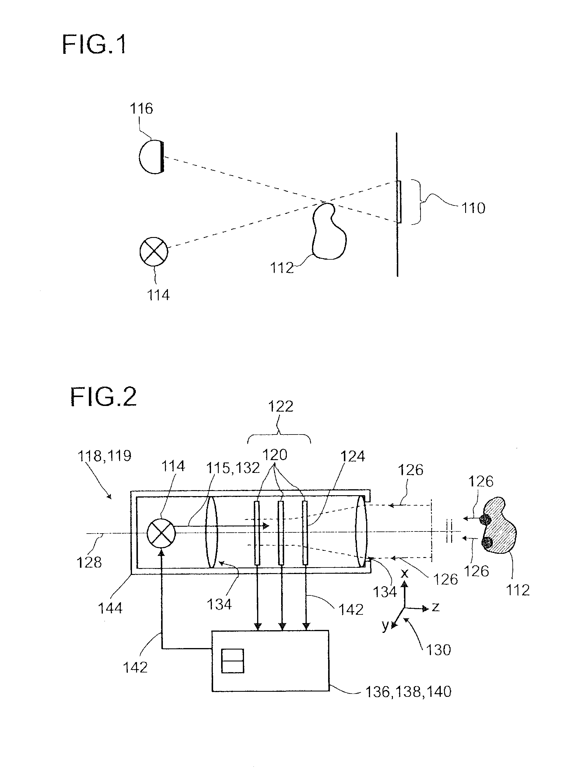
[0344]In FIG. 1, the occurrence of a shadow 110 in the determination of a position of at least one object 112 using an illumination source 114 and an imaging device 116 is depicted. The imaging device 116 may be arranged displaced from an optical axis of the illumination source 114. A light beam emitted by the illumination source 114 may illuminate a point and / or a region of the object 112. However, the displacement of the illumination 114 and the imaging device 116 may cause a shadow 110. The shadow 110 may be a region which in principle can be viewed by the imaging device 116, but which is not illuminated by the illumination source 114. In addition, a position of the shadow 110 may depend on the relative arrangement of the illumination source 114 and the imaging device 116.

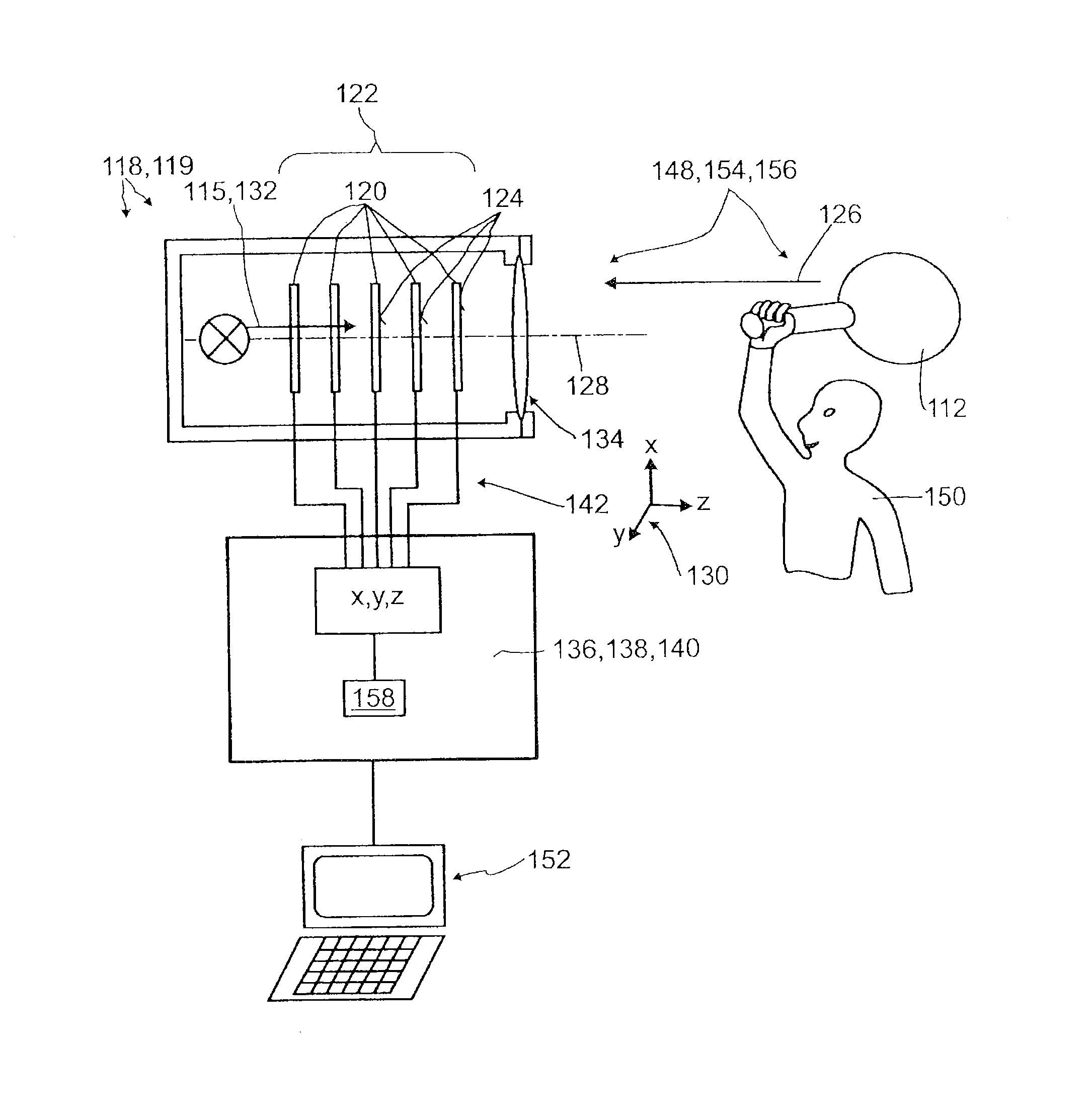
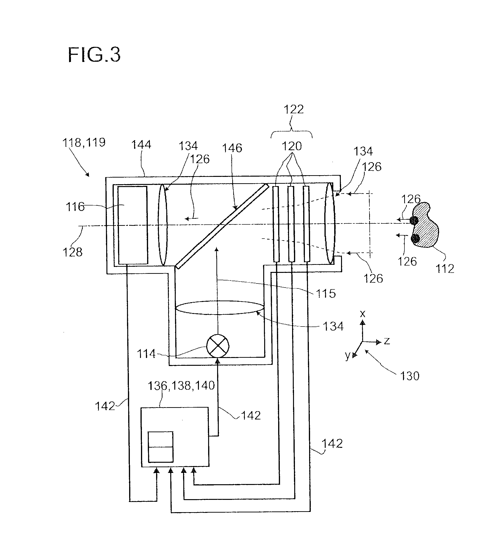
[0345]FIG. 2 shows an embodiment of a detector 118 according to the present invention, for determining a position of at least one object 112. The detector 118 in this embodiment or other embodiments of the prese...


PUM


Abstract

A detector (118) for determining a position of at least one object (112) is disclosed, the detector (118) comprising:
    • at least one longitudinal optical sensor (120), wherein the longitudinal optical sensor (120) has at least one sensor region (124), wherein the longitudinal optical sensor (120) is at least partially transparent, wherein the longitudinal optical sensor (120) is designed to generate at least one longitudinal sensor signal in a manner dependent on an illumination of the sensor region (124) by at least one light beam (126) traveling from the object (112) to the detector (118), wherein the longitudinal sensor signal, given the same total power of the illumination, is dependent on a beam cross-section of the light beam (126) in the sensor region (124);
    • at least one illumination source (114) adapted to illuminate the object (112) with illumination light (115) through the longitudinal optical sensor (120); and
    • at least one evaluation device (136), wherein the evaluation device (136) is designed to generate at least one item of information on a longitudinal position of the object (112) by evaluating the longitudinal sensor signal.

Description

FIELD OF THE INVENTION[0001]The invention relates to a detector for determining a position of at least one object, a human-machine interface, a tracking system, a camera, a method for determining a position of at least one object and various uses of the detector. Such devices and such methods can be employed for example in various areas of daily life, traffic technology, production technology, security technology, medical technology, entertainment technology or in the sciences. Additionally or alternatively, the application may be applied in the field of mapping of spaces, such as for generating maps of one or more rooms, one or more buildings or one or more streets. Further, the detector may form a camera or may be part of a camera for imaging at least one object. However, other applications are also possible in principle.PRIOR ART[0002]A large number of detectors configured to determine a position of an object are known from the prior art. Such detectors for determining the positi...

Claims


Application Information

Patent Timeline
IPC IPC(8): G06F3/03A63F13/213G06F3/01G01B11/14G02B27/10G01S17/32G01S17/86G01S17/89
CPCG06F3/0325G01B11/14A63F2300/1093G06F3/017A63F13/213G02B27/10G01S17/32G01S17/42G01S17/46G01S3/783G01S7/4816G01S7/4817G01S17/89G01S7/497G01S7/4812G01S17/86G06F3/011A63F13/428G02B27/144
Inventor SEND, ROBERTBRUDER, INGMARTHIEL, ERWINIRLE, STEPHAN
Owner BASF AG
Why Eureka
Try Eureka