Distortion-immune position tracking using redundant measurements

a technology of magnetic position tracking and redundant measurements, applied in the field of magnetic position tracking systems, can solve problems such as containing a significant amount of redundant information

Active Publication Date: 2008-02-07
BIOSENSE WEBSTER INC
View PDF23 Cites 54 Cited by
  • Summary
  • Abstract
  • Description
  • Claims
  • Application Information

AI Technical Summary

Benefits of technology

[0007]The system comprises two or more field generators that generate magnetic fields in the vicinity of the tracked object. The magnetic fields are sensed by a position sensor associated with the object and converted to position signals that are used to calculate the position (location and orientation) coordinates of the object. The system performs redundant field strength measurements and exploits the redundant information to reduce the measurement errors caused by the presence of field-distorting objects.
[0052]There is also provided, in accordance with an embodiment of the present invention, a computer software product used in a system for tracking a position of an object, the product including a computer-readable medium, in which program instructions are stored, which instructions, when read by the computer, cause the computer to control two or more field generators so as to generate magnetic fields in a vicinity of the object, to accept measurements of field strengths of the magnetic fields performed by a field sensor associated with the object, the measurements including redundant location information, wherein at least some of the measurements are subject to a distortion, and to determine location coordinates of the object relative to the two or more field generators by applying to the measurements a coordinate correcting function that exploits the redundant location information so as to reduce an impact of the distortion on the location coordinates.

Problems solved by technology

The 27 measurements are used to calculate the six location and orientation coordinates of the tracked object, thus containing a significant amount of redundant information.

Method used


Image

  • Distortion-immune position tracking using redundant measurements
  • Distortion-immune position tracking using redundant measurements
  • Distortion-immune position tracking using redundant measurements

Examples


Embodiment Construction

System Description

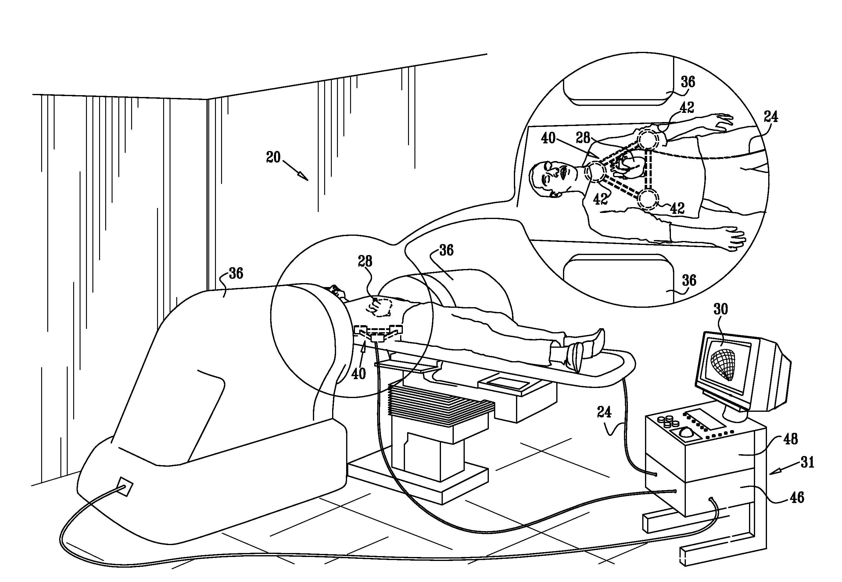
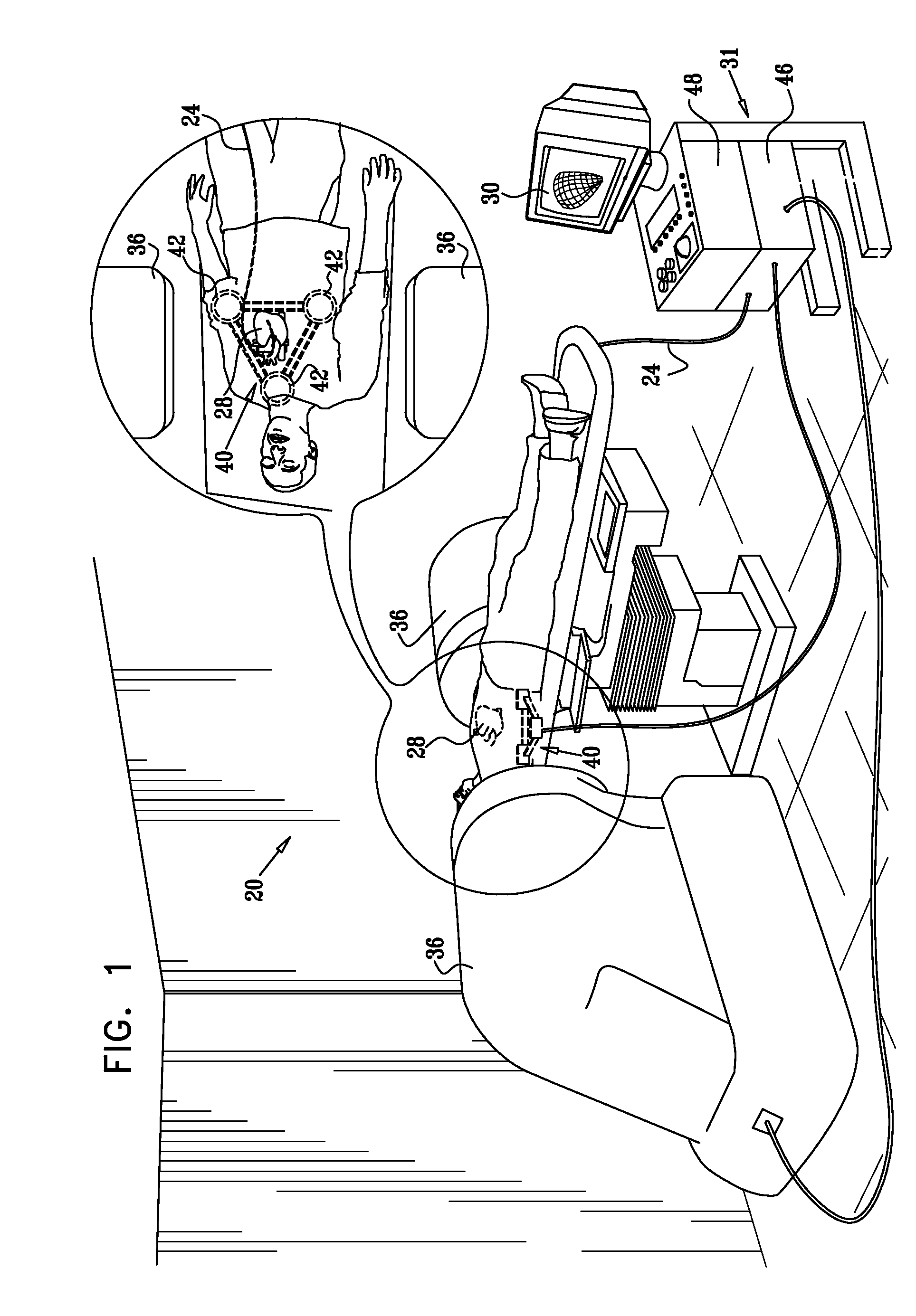
[0060]FIG. 1 is a schematic, pictorial illustration of a system 20 for position tracking and steering of intrabody objects, in accordance with an embodiment of the present invention. System 20 tracks and steers an intrabody object, such as a cardiac catheter 24, which is inserted into an organ, such as a heart 28 of a patient. System 20 also measures, tracks and displays the position (i.e., the location and orientation) of catheter 24. In some embodiments, the catheter position is registered with a three-dimensional model of the heart or parts thereof. The catheter position with respect to the heart is displayed to a physician on a display 30. The physician uses an operator console 31 to steer the catheter and to view its position during the medical procedure.

[0061]System 20 can be used for performing a variety of intra-cardiac surgical and diagnostic procedures in which navigation and steering of the catheter is performed automatically or semi-automatically by the...


PUM


Abstract

A method for tracking a position of an object includes using a field sensor associated with the object to measure field strengths of magnetic fields generated by two or more field generators, wherein a measurement of at least one of the field strengths is subject to a distortion. Rotation-invariant location coordinates of the object are calculated responsively to the measured field strengths. Corrected location coordinates of the object are determined by applying to the rotation-invariant location coordinates a coordinate correcting function so as to adjust a relative contribution of each of the measured field strengths to the corrected location coordinates responsively to the distortion in the measured field strengths.

Description

FIELD OF THE INVENTION[0001]The present invention relates generally to magnetic position tracking systems, and particularly to methods and systems for performing accurate position measurements in the presence of field-distorting objects.BACKGROUND OF THE INVENTION[0002]Various methods and systems are known in the art for tracking the coordinates of objects involved in medical procedures. Some of these systems use magnetic field measurements. For example, U.S. Pat. Nos. 5,391,199 and 5,443,489, whose disclosures are incorporated herein by reference, describe systems in which the coordinates of an intrabody probe are determined using one or more field transducers. Such systems are used for generating location information regarding a medical probe or catheter. A sensor, such as a coil, is placed in the probe and generates signals in response to externally-applied magnetic fields. The magnetic fields are generated by magnetic field transducers, such as radiator coils, fixed to an extern...

Claims


Application Information

Patent Timeline
Patent Type & Authority Applications(United States)
IPC IPC(8): A61B5/05G01R19/00
CPCA61B5/062A61B19/5244A61B2017/00725A61B2019/4894G01V3/081A61B2019/5251A61B2019/5272G01D5/2086G01R33/025A61B2019/505A61B2090/0818A61B2034/2072A61B34/20A61B2034/105A61B2034/2051A61B17/00H02N15/00
Inventor BAR-TAL, MEIRGOVARI, ASSAF
Owner BIOSENSE WEBSTER INC
Why Eureka
Try Eureka