Unlock instant, AI-driven research and patent intelligence for your innovation.

Packet forwarding device

Inactive Publication Date: 2009-03-12
FUJITSU LTD
View PDF16 Cites 3 Cited by
  • Summary
  • Abstract
  • Description
  • Claims
  • Application Information

AI Technical Summary

Benefits of technology

[0013]These together with other aspects and advantages which will be subsequently apparent, reside in the details of construction and operation as more fully h

Problems solved by technology

In the patent document, however, there is no description about the technology for swiftly settling down the congestion once occurred.

Method used


Image

  • Packet forwarding device
  • Packet forwarding device
  • Packet forwarding device

Examples


Embodiment Construction

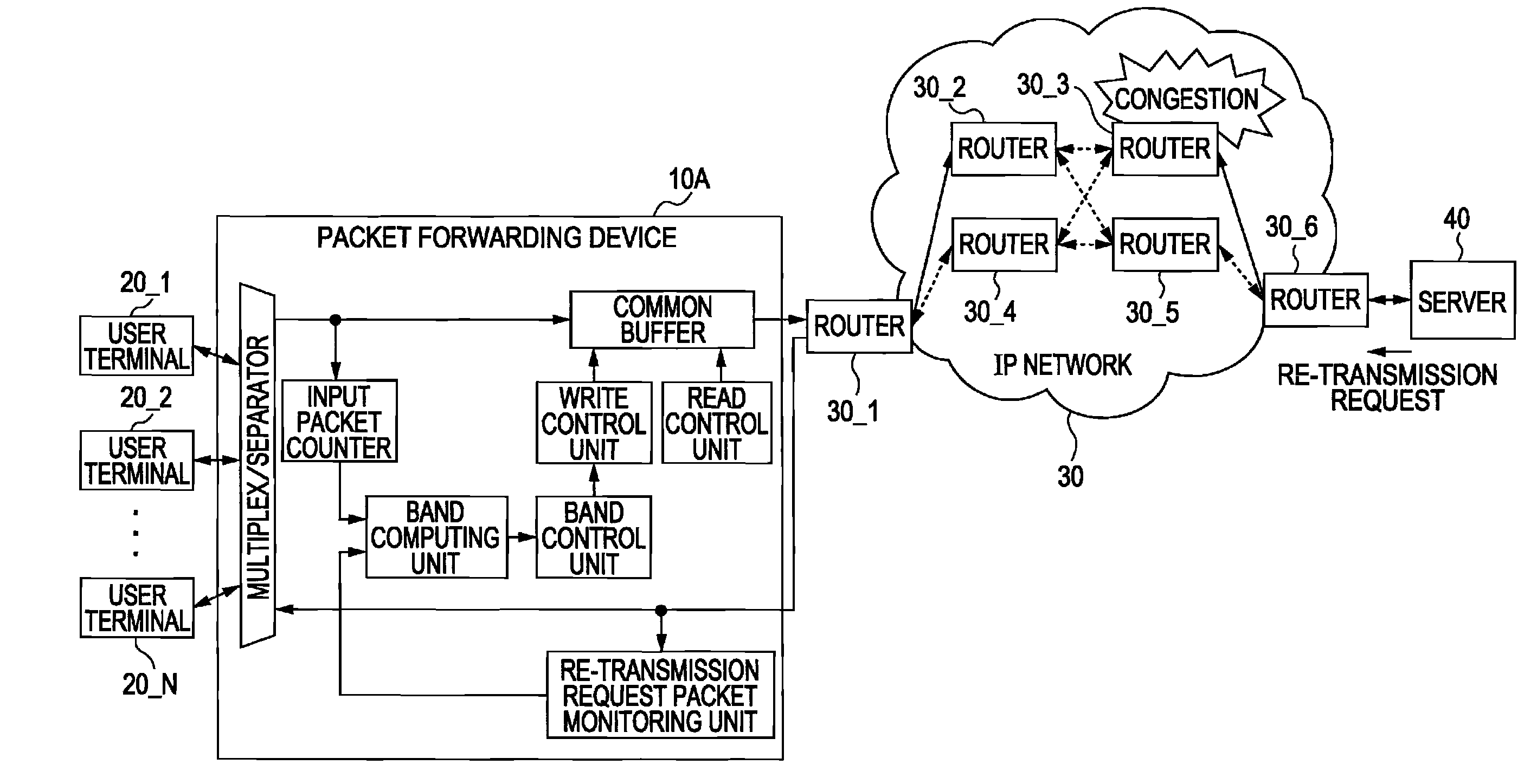
[0020]One example embodiment of the present invention will be described with reference to the accompanying drawings. FIG. 4 is an internal block diagram showing a packet forwarding device which is an embodiment of the present invention. In FIG. 4, like reference symbols are used for designating like or equivalent components in the conventional packet forwarding device shown in FIG. 1.

[0021]FIG. 5 is a model diagram showing a congestion occurring in one of the routers in an IP network when the packet forwarding device shown in FIG. 4 is employed. Also in FIG. 5, like reference symbols are used for designating like or equivalent components in FIG. 2.

[0022]A packet forwarding device 10A shown in FIG. 4 includes a re-transmission request packet monitoring unit 17 and a band computing unit 18, in addition to the components contained in the packet forwarding device 10 shown in FIG. 1.

[0023]The re-transmission request packet monitoring unit 17 monitors, for each user terminal, a passage of...


PUM


Abstract

A packet forwarding device reads each packet from a common buffer at a predetermined band velocity and transfers the readout packet; detects passage of a re-transmission request packet requesting re-transmission of a packet having been transmitted, from a receiving terminal to a packet transmission source; and limits a writing band of writing a packet transmitted from the packet transmission source terminal, which is a receiving terminal to which the re-transmission request packet is destined, into the common buffer when the re-transmission request packet is detected.

Description

CROSS-REFERENCE TO RELATED APPLICATIONS[0001]This application is related to and claims priority to Japanese patent application no. 2007-068523 filed on Mar. 16, 2007 in the Japan Patent Office, and incorporated by reference herein.BACKGROUND[0002]1. Field[0003]The present invention relates to a packet forwarding method, device, and computer readable medium thereof, which temporarily stores packets transmitted from a plurality of transmission source terminals into a common buffer, reads out the packets from the common buffer at a given band velocity, and transfers the readout packets to other terminals.[0004]2. Description of the Related Art[0005]The packet forwarding devices as just mentioned are located in a network in which packet data flows. FIG. 1 is an internal block diagram showing a conventional packet forwarding device. The packet forwarding device 10 is constituted by a multiplex / separator 11, a common buffer 12, an input packet counter 13, a band control unit 14, a write c...

Claims


Application Information

Patent Timeline
IPC IPC(8): H04L12/26H04L12/801H04L12/811H04L12/911H04L29/08
CPCH04L47/10H04L47/25H04L47/22H04L47/11
Inventor IWAKIRI, MASAHIKOSHIWACHI, SHINICHI
Owner FUJITSU LTD