Dynamic Prediction of Traffic Congestion by Tracing Feature-Space Trajectory of Sparse Floating-Car Data

a feature-space trajectory and traffic congestion technology, applied in the direction of vehicle position indication, instruments, analogue processes for specific applications, etc., can solve the problems of not always running the probe car in all the road sections, and the traffic situation cannot be predicted

Inactive Publication Date: 2009-03-12
HITACHI LTD
View PDF0 Cites 16 Cited by
  • Summary
  • Abstract
  • Description
  • Claims
  • Application Information

AI Technical Summary

Problems solved by technology

However, the probe car is not always running in all the road sections.
Hence, in the road section in which the probe car is not running, and the necessary time at present is not measured, the traffic situation can not be predicted.

Method used


Image

  • Dynamic Prediction of Traffic Congestion by Tracing Feature-Space Trajectory of Sparse Floating-Car Data
  • Dynamic Prediction of Traffic Congestion by Tracing Feature-Space Trajectory of Sparse Floating-Car Data
  • Dynamic Prediction of Traffic Congestion by Tracing Feature-Space Trajectory of Sparse Floating-Car Data

Examples


embodiment 1

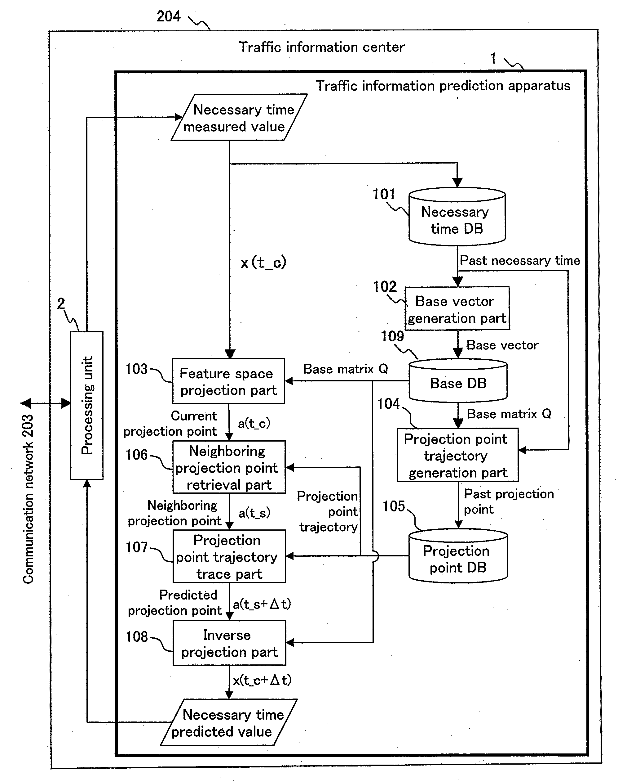
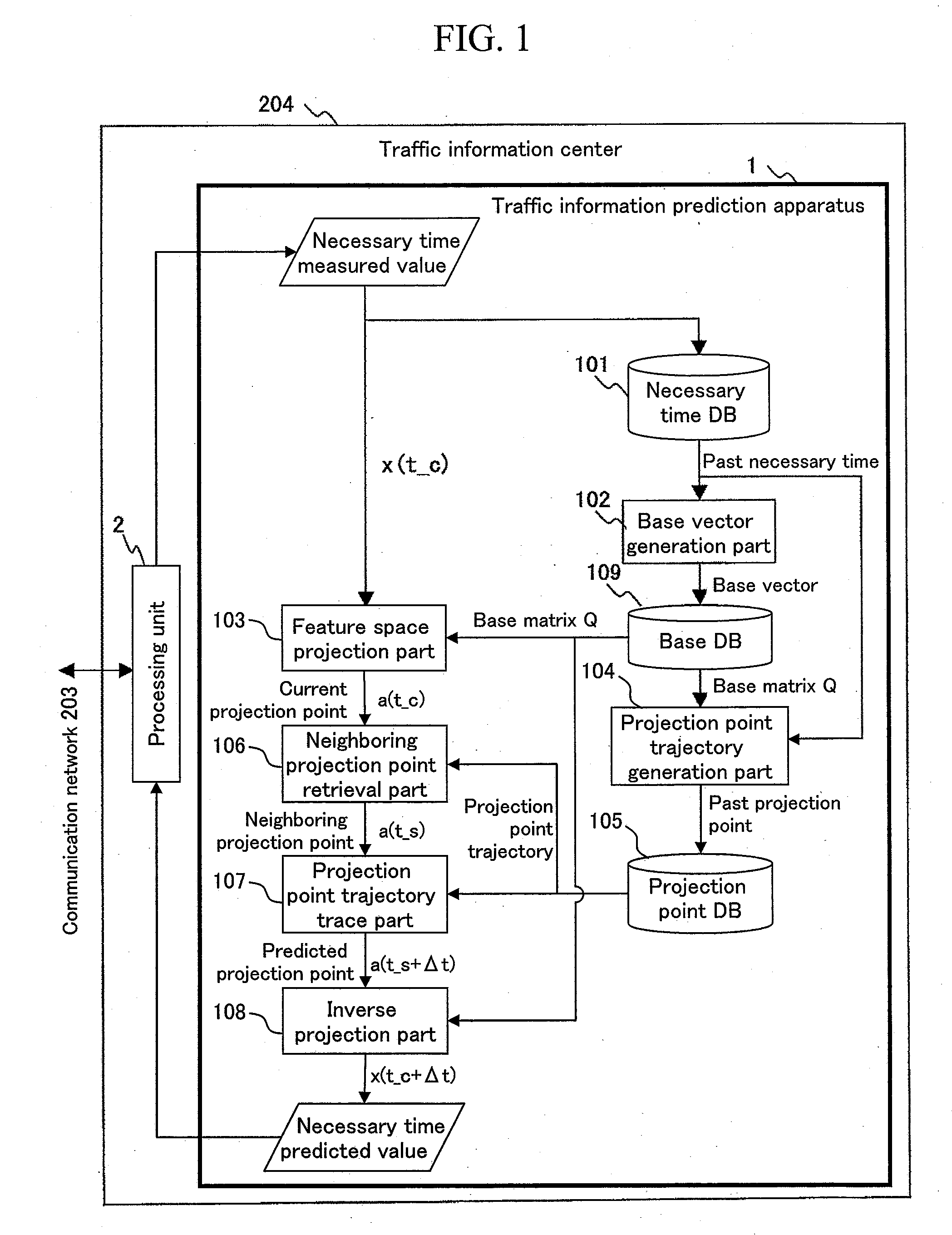
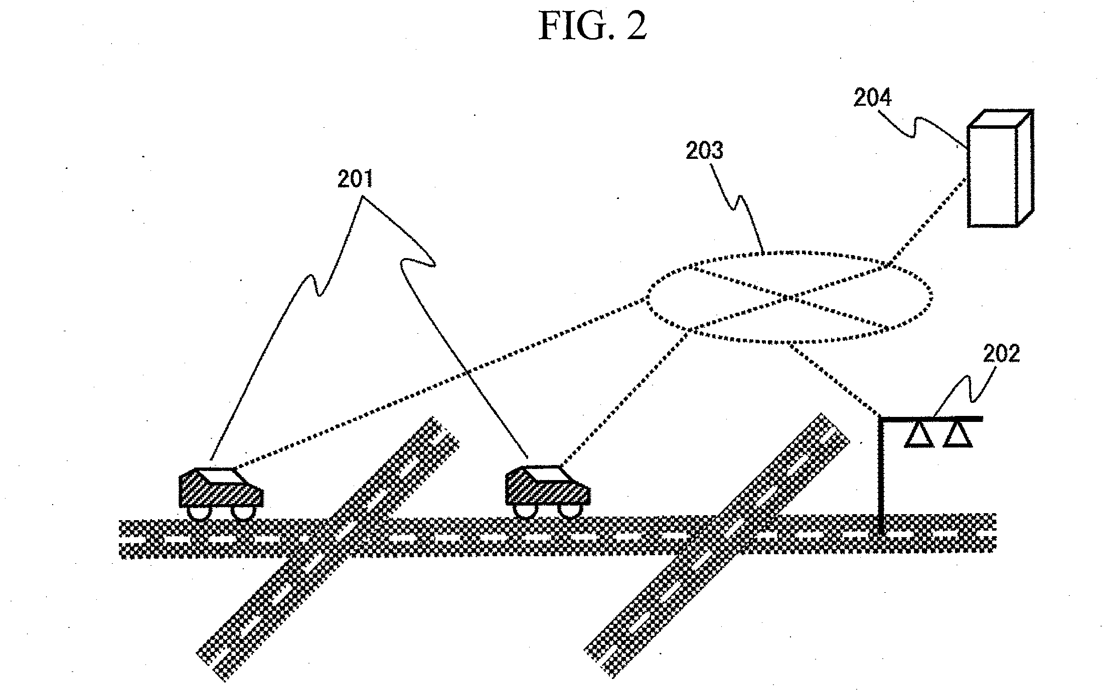
[0023]FIG. 1 is a diagram showing an example of the configuration of a traffic information prediction apparatus according to an embodiment of the invention. A necessary time database (hereinafter, a necessary time DB) 101 is a storage unit that records the necessary time for each link inputted into the traffic information prediction apparatus 1. Herein, the link means a road section as the unit in processing the traffic information, such as a road section between main intersections. As regards the necessary time for each link, data (probe car data) collected by a probe car 201 on a road network and road sensor data measured by a road sensor 202 are transmitted to a traffic information center 204 having the traffic information prediction apparatus 1 across a communication network 203, as shown in FIG. 2.

[0024]In the traffic information center 204, the received data is converted into the necessary time on the concerned link by a processing unit 2, and inputted into the traffic informa...

embodiment 2

[0048]A modified embodiment having a different way of obtaining the predicted projection point from the embodiment 1 will be described below. In the embodiment 1, since the feature point trajectory draws the periodic trajectory, the neighboring projection pint is obtained by retrieving the projection point history of the past traffic situation data in the neighborhood of the feature point corresponding to the present traffic situation from the projection point DB 105, and the predicted projection point is obtained by tracing the projection point trajectory, starting from the retrieved projection point. On the contrary, the embodiment 2 is the same as the embodiment 1, except that a plurality of predicted projection points are obtained by retrieving a plurality of neighboring projection points, without using the single neighboring projection point, but, and the necessary time is predicted based on its representative value.

[0049]Specifically, instead of the neighboring projection poin...


PUM


Abstract

A traffic situation is predicted based on the correlation in the traffic situation between road sections. A base vector generation unit generates the base vectors constituting a feature space representing the correlation between a plurality of links by making a principal component analysis for the necessary time in the past recorded in a necessary time database. A projection point trajectory generation unit records a projection point trajectory of projecting the necessary time in the past recorded in the necessary time database to the feature space in a projection point database. A feature space projection unit projects the necessary time at present to the feature space, and a neighboring projection point retrieval unit retrieves a past projection point in the neighborhood of the concerned projection point from the projection point database, and a projection point trajectory trace unit traces the trajectory of past projection points starting from the retrieved neighboring projection point for a prediction target time width, and an inverse projection unit inversely projects the end point of the concerned trajectory to calculate the predicted value of the necessary time.

Description

BACKGROUND OF THE INVENTION[0001]1. Field of the Invention[0002]The present invention relates to a traffic situation prediction apparatus and a traffic situation prediction method for predicting a change in the traffic situation in the future from the traffic situation in the past.[0003]2. Background Art[0004]Conventionally, a probe car is often used to predict a traffic situation on the road. The probe car is the vehicle that mounts the in-car equipment comprising various sensors and a communication apparatus to collect data such as vehicle position and traveling speed from various sensors, and transmit the collected data (hereinafter probe car data) to a predetermined traffic information center. The probe car is often a taxi in cooperation with a taxi company, or a private car under the contract with the user as a part of traffic information services intended for the private car, for example.[0005]JP Patent Publication (Kokai) No. 2004-362197 disclosed the invention for predicting...

Claims


Application Information

Patent Timeline
Patent Type & Authority Applications(United States)
IPC IPC(8): G06F19/00G08G1/00G08G1/01G08G1/13
CPCG08G1/0104G08G1/0112G08G1/0116G08G1/0129G08G1/0141
Inventor KUMAGAI, MASATOSHIHIRUTA, TOMOAKIOKUDE, MARIKOTANIKOSHI, KOICHIRO
Owner HITACHI LTD
Why Eureka
Try Eureka