Method of recording data in multilayered recordable optical recording medium, recording and reproducing apparatus for recording the data in the recording medium and the recording medium

a multi-layer recordable optical recording medium and recording apparatus technology, applied in mechanical recording, recording signal processing, instruments, etc., can solve the problems of large-scale hard disk development, insufficient recording capacity, and insufficient blue laser medium capacity, so as to achieve suitable recording conditions and effectively utilize recording capacity.

Active Publication Date: 2009-03-19
RICOH KK
View PDF22 Cites 12 Cited by
  • Summary
  • Abstract
  • Description
  • Claims
  • Application Information

AI Technical Summary

Benefits of technology

[0066]According to an embodiment of the present invention, when test recording is executed in a multilayered recordable optical recording medium having N recording layers (N is an integer of 2 or more), a test recording range in a test recording area of an (m+1)th recording layer is shifted relative to a test recording range in a test recording area of an mth recording layer by an amount greater than a difference of decentration amounts between the mth and the (m+1)th recording layers or a maximum decentration amount in the N recording layers. The shifting direction is inverse to a test recording range adding direction in a radius direction of the recording medium. Therefore, suitable recording conditions can be effectively obtained and recording capacity can be effectively utilized in the recording medium.

Problems solved by technology

Meanwhile, a large capacity HD (hard disk) has been developed; however, the recording capacity is not sufficient, and even recording media such as a CD (compact disk), a DVD (digital versatile disk), and a medium using a blue laser have not had sufficient capacity.
That is, very complicated information management is required and detailed power control is required.
Especially, when the number of the recording layers is increased, the number of the information recorded status flags to be managed is increased; therefore, Patent Document 1 may not be effectively used in a multilayered optical recording medium in which the number of the recording layers is three or more.
In addition, as shown in FIGS. 29 (e) and (f), even if the information has been recorded in the second recording layer, an information unrecorded part may exist in the second recording layer due to, for example, defects.
Consequently, suitable information recording in the first recording layer may not be executable.
The defective recording is generated when the transmission rate is changed or dispersed.
Consequently, the recording conditions in the recording layer where the information is to be recorded may not be optimum by using only the recorded status of the recording layer where the information has been recorded positioned in front of the recording layer where the information is to be recorded.
However, in the zones A2, B2, and C2, having no dispersion of recording quality and no unrecorded part are not assured.
In order to make the reliability of the suitable recording conditions in the first recording layer high, the width of the zone is narrowed; however, the number of the zones to be managed is increased and this is not practical.
However, when the number of the layers is increased, the number of combinations of the recorded statuses of the layers is increased, and the capacity of the power test areas may not be sufficient.
In order to obtain high reliability of the power test, a width having a certain size or more is required in the front-positioned recording layers in the radius direction; however, since a sufficient width cannot be obtained, sufficient capacity of the power test area cannot be obtained.
However, when the recorded statuses of the (K+1) and (K+2) layers are not ideal, the suitable recording conditions with high reliability cannot be obtained in the K layer.
The suitable recording conditions in the K layer are different between statuses shown in FIGS. 32 (a) and (b); however, Patent Document 2 does not teach how to handle the difference.
However, Patent Document 3 has the following problems.
However, actually, the test recording cannot be executed on all the combinations; therefore, high recording reliability on the K layer may not be obtained.
Consequently, the recording reliability in the K layer may not be sufficient.
Therefore, when the number of the recording layers at the front side is increased, the suitable recording conditions in the recording layer where information is to be recorded cannot be determined by conventional OPC.
That is, it is difficult to realize this in an actual situation.

Method used


Image

  • Method of recording data in multilayered recordable optical recording medium, recording and reproducing apparatus for recording the data in the recording medium and the recording medium
  • Method of recording data in multilayered recordable optical recording medium, recording and reproducing apparatus for recording the data in the recording medium and the recording medium
  • Method of recording data in multilayered recordable optical recording medium, recording and reproducing apparatus for recording the data in the recording medium and the recording medium

Examples


first embodiment

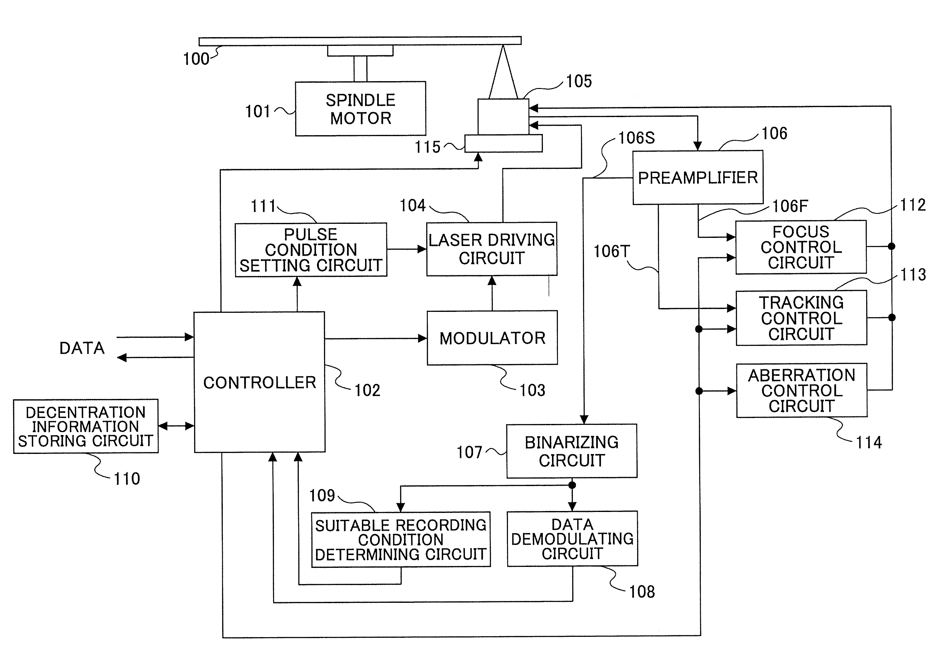
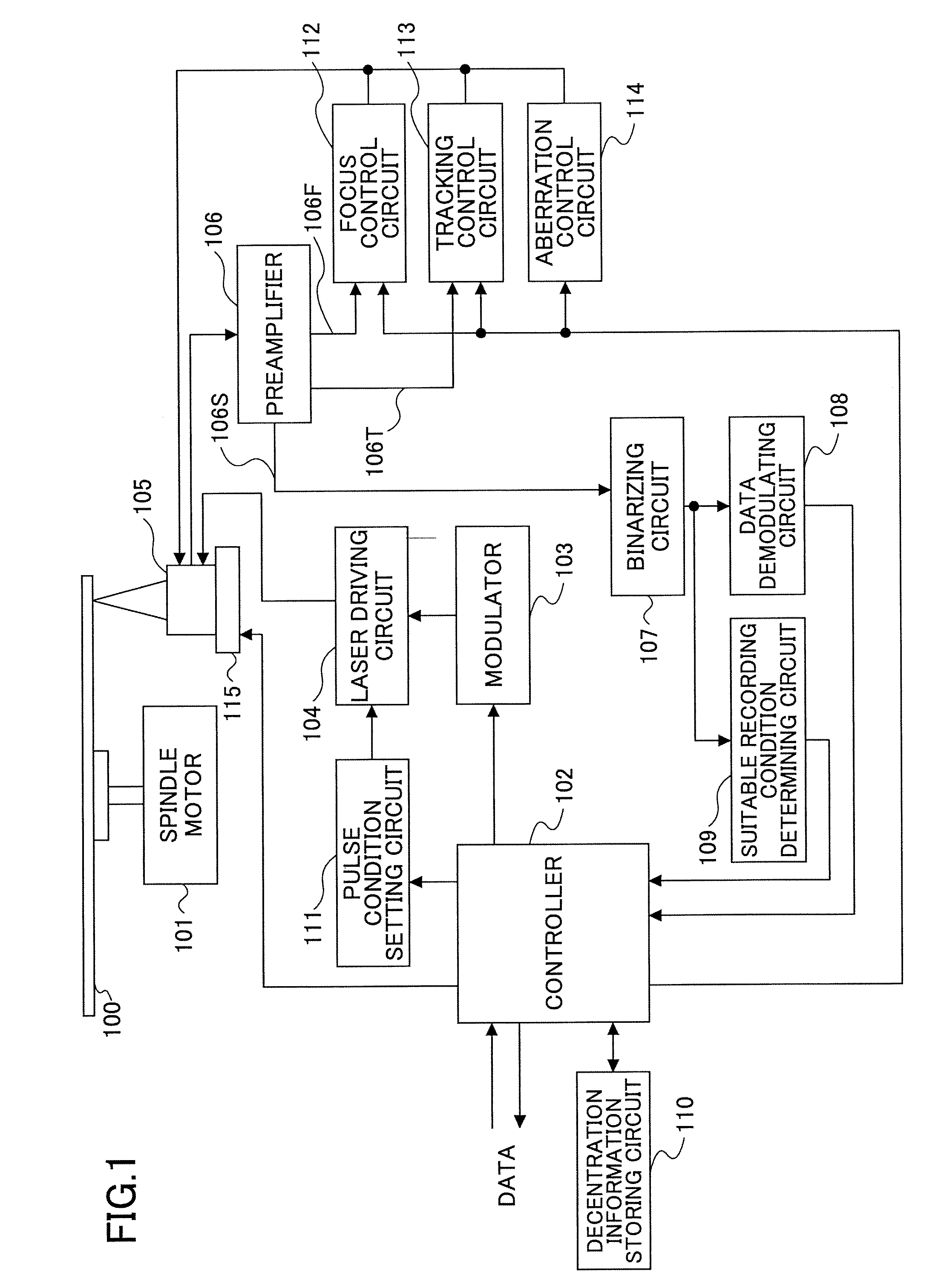
[0103]FIG. 1 is a block diagram showing a recording and reproducing apparatus according to a first embodiment of the present invention.

[0104]In FIG. 1, a multilayered recordable optical recording medium 100 (disk) has been attached to the recording and reproducing apparatus.

[0105]As shown in FIG. 1, the recording and reproducing apparatus includes a spindle motor 101, a controller 102, a modulator 103, a laser driving circuit 104, an optical head 105, a preamplifier 106, a binarizing circuit 107, a data demodulating circuit 108, a suitable recording condition determining circuit 109, a decentration information storing circuit 110, a pulse condition setting circuit 111, a focus control circuit 112, a tracking control circuit 113, an aberration control circuit 114, and a moving unit 115.

[0106]The spindle motor 101 drives the multilayered recordable optical recording medium 100. The controller 102 controls operations of the recording and reproducing apparatus. The modulator 103 modulat...

second embodiment

[0171]FIG. 17 is a block diagram showing a recording and reproducing apparatus according to a second embodiment of the present invention. In the second embodiment of the present invention, when an element is similar to or the same as that in the first embodiment of the present invention, the same reference number as that in the first embodiment of the present invention is used for the element, and the same description as that in the first embodiment of the present invention is omitted.

[0172]As shown in FIG. 17, when the block diagram shown in FIG. 17 is compared with that shown in FIG. 1, a decentration amount detecting circuit 116 is newly added to the second embodiment of the present invention. The decentration amount detecting circuit 116 detects a decentration amount of each recording layer based on a tracking signal from the tracking control circuit 113.

[0173]First, the recording and reproducing apparatus initializes the multilayered recordable optical recording medium 100. Spe...

third embodiment

[0203]FIG. 24 is a schematic diagram showing a first case of test recording according to a third embodiment of the present invention.

[0204]In the first case of the third embodiment of the present invention, data have been recorded in all parts of the data area of the first recording layer after the first test recording; therefore, second test recording is executed from the second recording layer.

[0205]In the first and second embodiments of the present invention, when a multilayered recordable optical recording medium 100 is attached to a recording and reproducing apparatus, test recording is executed in all the recording layers of the multilayered recordable optical recording medium 100, and suitable recording conditions are determined in each of all the recording layers.

[0206]However, in the third embodiment of the present invention, when actual recording is requested, the OPC process may be applied only to a recording layer (farthest recordable recording layer) where the actual re...


PUM

PropertyMeasurementUnit
areaaaaaaaaaaa
shifting distanceaaaaaaaaaa
βaaaaaaaaaa

Abstract

A method of recording data in a multilayered recordable optical recording medium is disclosed. When test recording is executed in a multilayered recordable optical recording medium having N recording layers (N is an integer of 2 or more), a test recording range in a test recording area of an (m+1)th recording layer is shifted relative to a test recording range in a test recording area of an mth recording layer by an amount greater than a difference of decentration amounts between the mth and the (m+1)th recording layers or a maximum decentration amount in the N recording layers. The shifting direction is inverse to a test recording range adding direction in a radius direction of the recording medium.

Description

BACKGROUND OF THE INVENTION[0001]1. Field of the Invention[0002]The present invention generally relates to a method of recording data in a multilayered recordable optical recording medium, a recording and reproducing apparatus for recording the data in the recording medium, and the recording medium.[0003]2. Description of the Related Art[0004]Recently, individual users have handled audio data, image data, and video data whose capacity is large. Meanwhile, a large capacity HD (hard disk) has been developed; however, the recording capacity is not sufficient, and even recording media such as a CD (compact disk), a DVD (digital versatile disk), and a medium using a blue laser have not had sufficient capacity.[0005]In order to increase the recording capacity, a multilayered optical recording medium has been developed. The multilayered optical recording medium is formed by stacking plural layers on a substrate.[0006]In a recording apparatus using the multilayered optical recording medium,...

Claims


Application Information

Patent Timeline
Patent Type & Authority Applications(United States)
IPC IPC(8): G11B7/20G11B7/26
CPCG11B7/00736G11B2007/0013G11B7/1267G11B7/0953
Inventor SASA, NOBORU
Owner RICOH KK
Why Eureka
Try Eureka