Connector With Redundant Terminal Locking

Inactive Publication Date: 2009-03-26
TE CONNECTIVITY CORP
View PDF7 Cites 20 Cited by
  • Summary
  • Abstract
  • Description
  • Claims
  • Application Information

AI Technical Summary

Benefits of technology

[0007]An advantage of exemplary embodiments of the invention is that terminal position assurance is accomplished through the use of a secondary locking feature which provides an added level of terminal retention within the connector.
[000

Problems solved by technology

Thus, if the latch breaks during assembly or use, the terminal can slide about within the connector or even slip out of the connector completely.
This results in undesirable performance and may lead to complete failure of the electrical connection accomplished with the connector.
This can be particularly problematic in sealed connectors, such as those us

Method used


Image

  • Connector With Redundant Terminal Locking
  • Connector With Redundant Terminal Locking
  • Connector With Redundant Terminal Locking

Examples


Example

[0019]Where like parts appear in more than one drawing, it has been attempted to use like reference numerals for clarity.

DETAILED DESCRIPTION OF EXEMPLARY EMBODIMENTS

[0020]Exemplary embodiments of the invention are directed to connectors having primary and secondary locking features to retain a particular terminal within a connector housing. The secondary locking feature also provides terminal positioning assurance, assisting in both the proper positioning of the terminal within the connector and in securing the terminal within the connector housing.

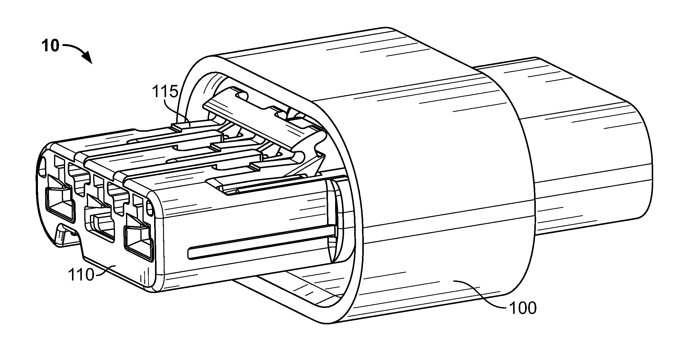
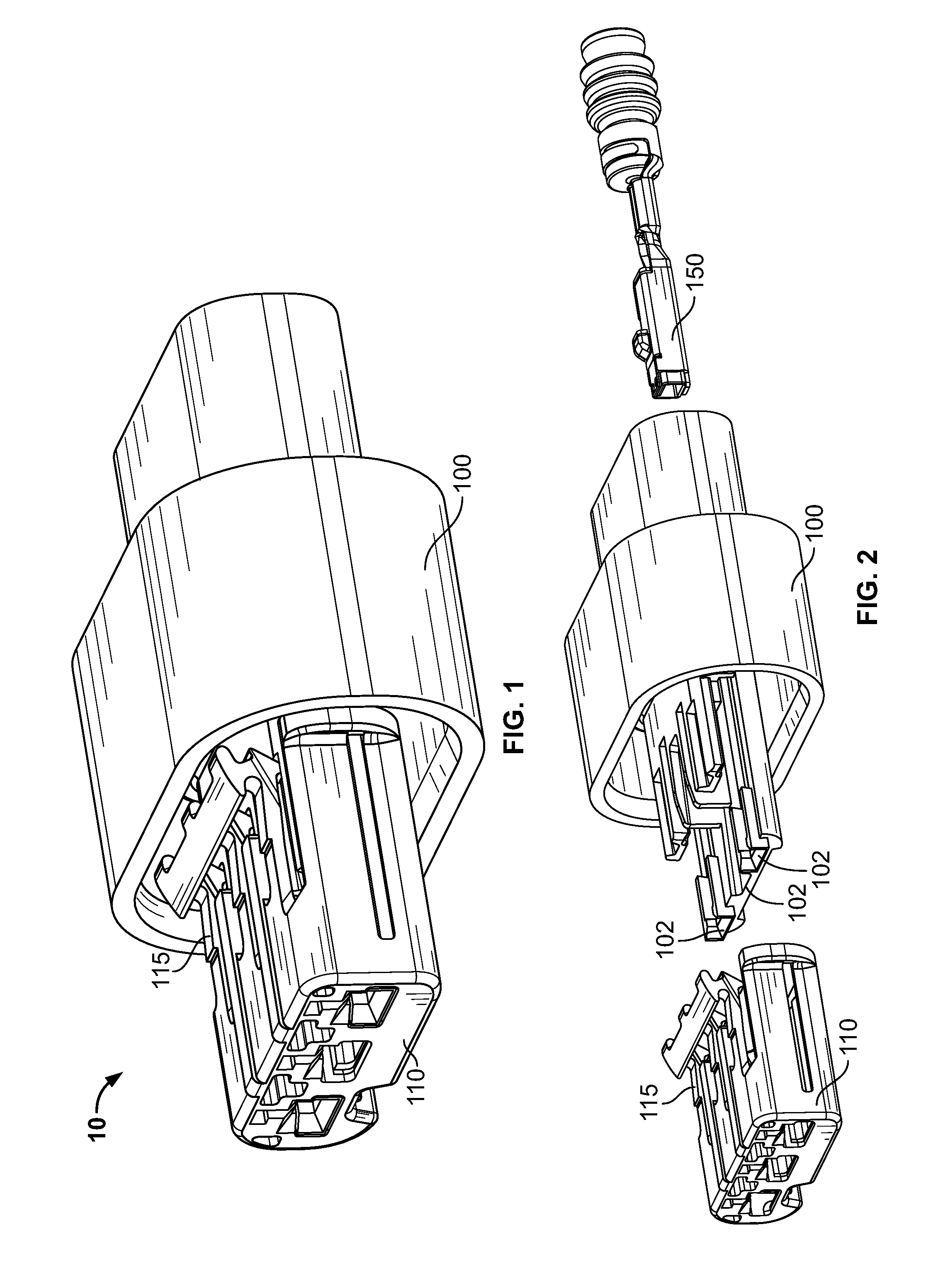
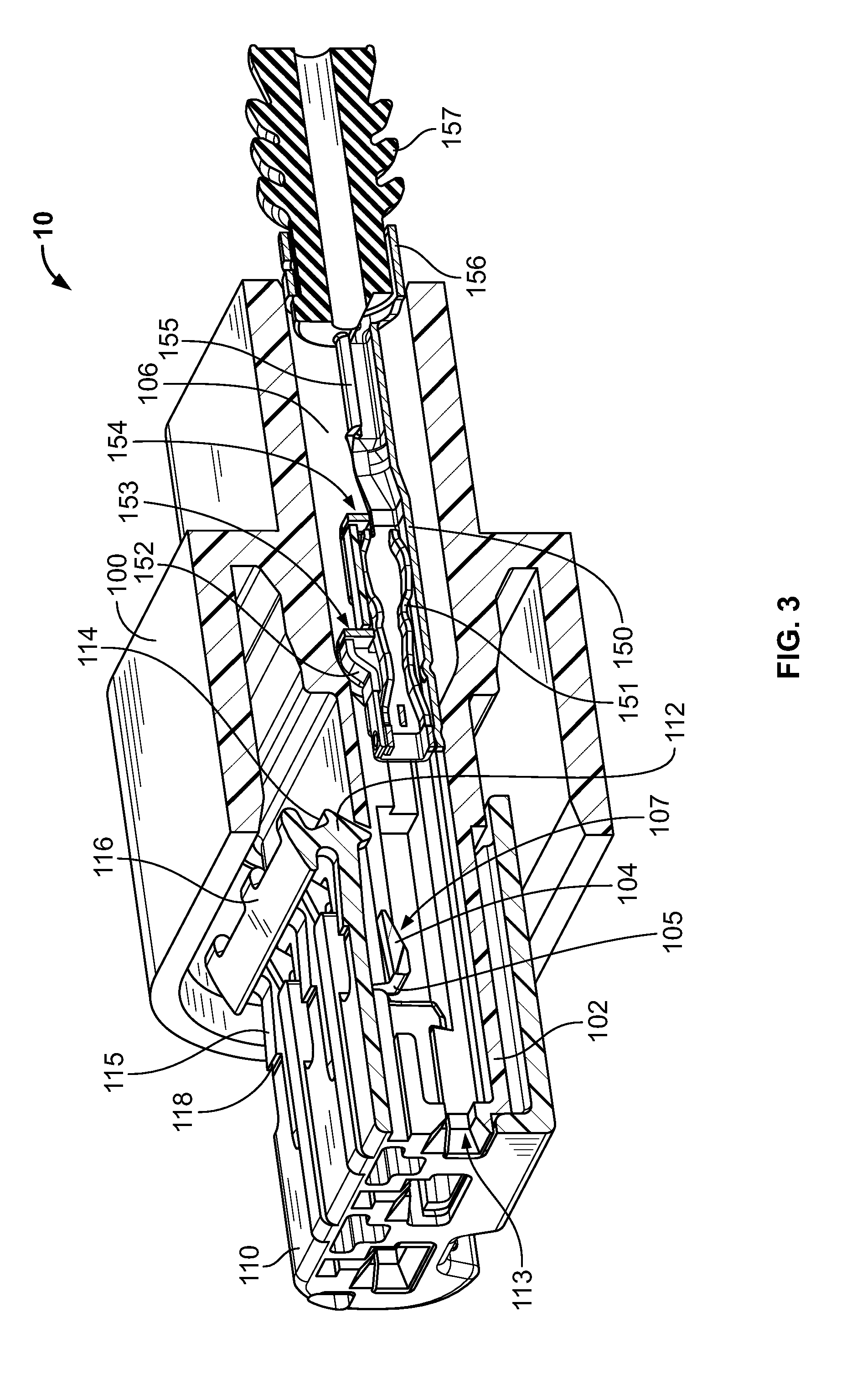
[0021]Referring to FIG. 1, a connector 10 is shown that includes a connector housing having a main connector housing 100 and a secondary connector housing 110 that has a locking hinge 115. As better seen in the exploded view in FIG. 2, the main connector housing 100 includes a terminal support 102 in which one or more terminals 150 can be seated. The terminals 150 can be used to terminate wires (not shown) that extend rearwardly from the...


PUM


Abstract

A connector is disclosed. The connector includes a connector housing having a terminal channel and a terminal positioned within the terminal channel. The connector includes a primary locking mechanism including a locking beam configured to engage a first terminal locking surface and a secondary locking mechanism including a locking hinge having a locking foot configured to engage a second terminal locking surface. The locking hinge is configured to pivot from a staging position to permit passage of the terminal into the connector through the terminal channel to an operative position to retain the terminal within the terminal channel and establish a position of maximum rearward travel of the terminal within the terminal channel.

Description

FIELD[0001]The present disclosure is directed to electrical connectors and more particularly to connectors that isolate and retain multiple terminals.BACKGROUND[0002]In current connector systems that use a plastic latch for primary terminal retention, the plastic latch often serves as the sole locking feature. Thus, if the latch breaks during assembly or use, the terminal can slide about within the connector or even slip out of the connector completely. This results in undesirable performance and may lead to complete failure of the electrical connection accomplished with the connector.[0003]This can be particularly problematic in sealed connectors, such as those used in the automotive and aviation industries, that are subjected to rigorous assembly and operating conditions. Despite the exposure to rigorous conditions, sealed connectors generally present complex tooling requirements and little available open space within the connector that further complicates efforts to adequately re...

Claims


Application Information

Patent Timeline
IPC IPC(8): H01R13/514
CPCH01R13/4223H01R13/506H01R13/501H01R13/4364
Inventor MARTIN, GALEN M.FORISKA, MATTHEW F.
Owner TE CONNECTIVITY CORP
Why Eureka
Try Eureka