Twin clutch speed-change apparatus

a technology of speed-change apparatus and clutch, which is applied in the direction of mechanical actuated clutches, interengaging clutches, gearing, etc., can solve the problems of shifting sound and/or shock, and achieve the effect of reducing shifting shock

Active Publication Date: 2009-04-02
HONDA MOTOR CO LTD
View PDF6 Cites 32 Cited by
  • Summary
  • Abstract
  • Description
  • Claims
  • Application Information

AI Technical Summary

Benefits of technology

[0008]It is an object of the present invention to solve the problem of the existing technique described above and to provide a twin clutch type spee

Problems solved by technology

There is a possibility that a flapping s

Method used


Image

  • Twin clutch speed-change apparatus
  • Twin clutch speed-change apparatus
  • Twin clutch speed-change apparatus

Examples


Embodiment Construction

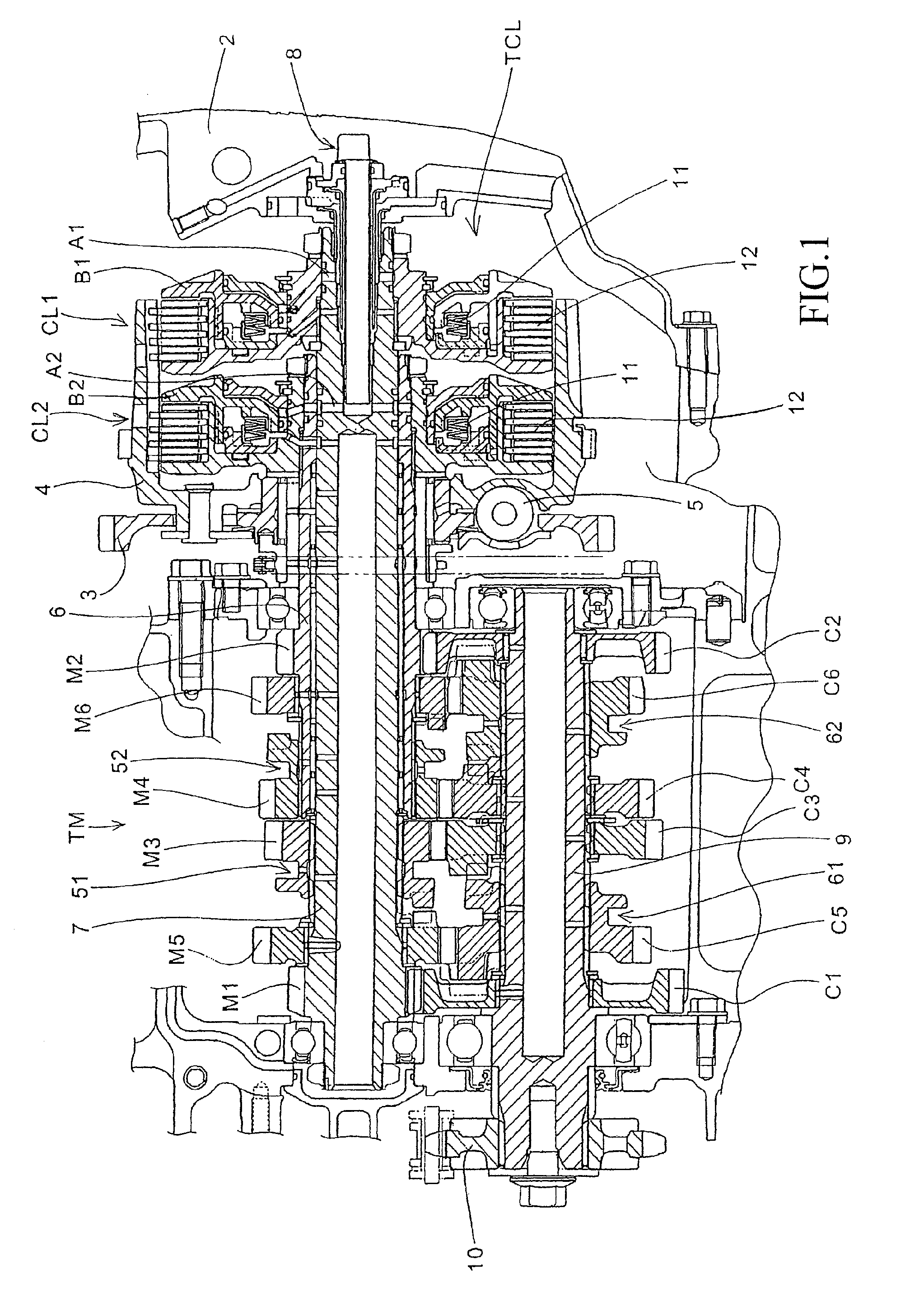
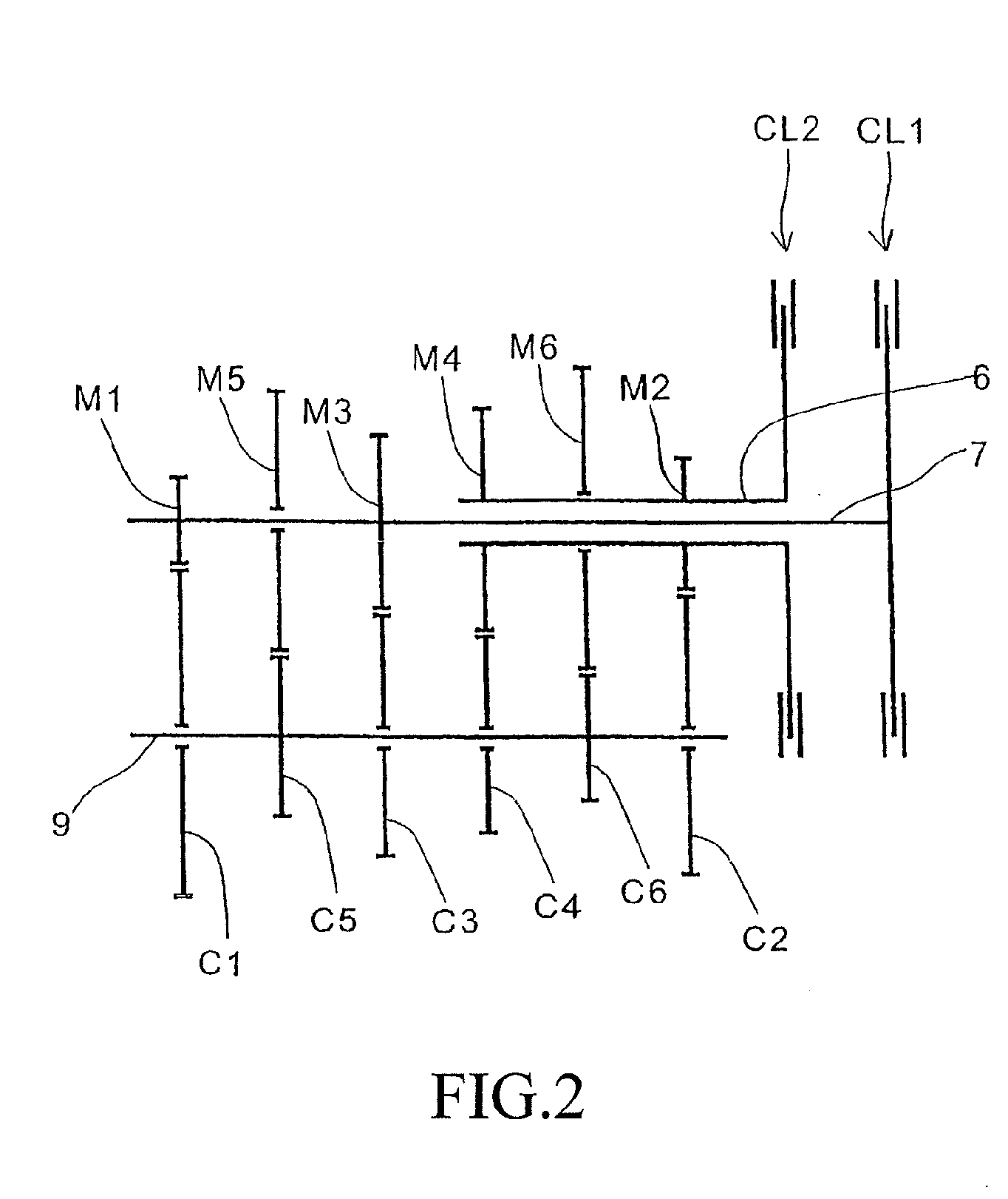
[0033]FIG. 1 is a cross-sectional view of a twin clutch type speed-change apparatus 1 according to an embodiment of the present invention. FIG. 2 is a skeleton diagram illustrating speed-change gear arrangement of the speed-change apparatus 1. The twin clutch speed-change apparatus includes a twin clutch TCL composed of a first clutch CL1 and a second clutch CL2, and a six-forward-speed sequential transmission TM. The speed-change apparatus is accommodated inside a crankcase 2 together with an engine (not shown) as a power source of a vehicle.

[0034]A rotational drive power is transmitted from a crankshaft (not shown) of the engine to a primary gear 3 having a shock absorbing mechanism 5. The rotational drive power is outputted therefrom to a countershaft 9 attached with a drive sprocket 10 through the twin clutch TCL, an outer main shaft 6 as an external tube, an inner main shaft 7 as an inner tube rotatably carried by the outer tube, and six gear pairs provided between the main sha...


PUM


Abstract

A twin clutch speed-change apparatus that can reduce shift shock includes a transmission with multiple gear pairs disposed between a main shaft and a countershaft. A twin clutch is provided on the main shaft, a rotational drive force from an engine being connected/disconnected between the transmission and the engine, a dog clutch is provided between an axially slidably attached slidable gear and an axially non-slidably attached non-slidable gear to select a gear pair, for transmitting a rotational drive force, from the multiple gear pairs. Dog teeth of the dog clutch include steps different in axial height from each other between a portion abutted against a lateral wall surface of a dog hole when the rotational drive force is transmitted by the dog clutch, and a portion abutted against a lateral wall surface of the dog hole when the rotational drive force is not transmitted by the dog clutch.

Description

CROSS-REFERENCE TO RELATED APPLICATION[0001]The present application claims priority under 35 U.S.C. §119 to Japanese Patent Application No. 2007-255125, filed Sep. 28, 2007, the entire contents of which are hereby incorporated by reference.BACKGROUND OF THE INVENTION[0002]1. Field of the Invention[0003]The present invention relates to twin clutch type speed-change apparatuses and, in particular, to a twin clutch type speed-change apparatus that reduces shift shock by providing a step on dog teeth provided on a speed-change gear sliding on a shaft.[0004]2. Description of Background Art[0005]Japanese Patent Laid-Open No. 2007-100739 discloses a multi-step transmission having a plurality of speed-change gear pairs configured such that shifting operation is executed by allowing shift forks parallel sliding on a main shaft and a countershaft to drive speed-change gears and sleeves slidable on the main shaft and the countershaft.[0006]In particular, this document discloses a twin clutch t...

Claims


Application Information

Patent Timeline
IPC IPC(8): F16H3/08F16H3/089
CPCF16D11/10F16D2011/008F16H3/006F16H3/16F16H63/30Y10T74/19242Y10T74/19228Y10T74/19288Y10T74/19372Y10T74/19358F16H2063/3093F16H57/028F16H61/04F16H3/091
Inventor TSUKADA, YOSHIAKIOZEKI, TAKASHIKOJIMA, HIROYUKINEDACHI, YOSHIAKISUGITA, HARUOMI
Owner HONDA MOTOR CO LTD
Why Eureka
Try Eureka