Inflator

a technology of inflator and inflator body, which is applied in the direction of vehicle components, pedestrian/occupant safety arrangements, vehicular safety arrangements, etc., can solve the problem of high demand for a reduction in the size of this type of inflator

Active Publication Date: 2009-04-02
DAICEL CHEM IND LTD
View PDF7 Cites 12 Cited by
  • Summary
  • Abstract
  • Description
  • Claims
  • Application Information

AI Technical Summary

Problems solved by technology

The attachment location of a stored gas type inflator, which is used in an air bag apparatus for a side collision protection or a curtain air bag apparatus, within a vehicle is restricted, and therefore demand for a reduction in size of this type of inflator is particularly high.

Method used


Image

  • Inflator
  • Inflator
  • Inflator

Examples


Embodiment Construction

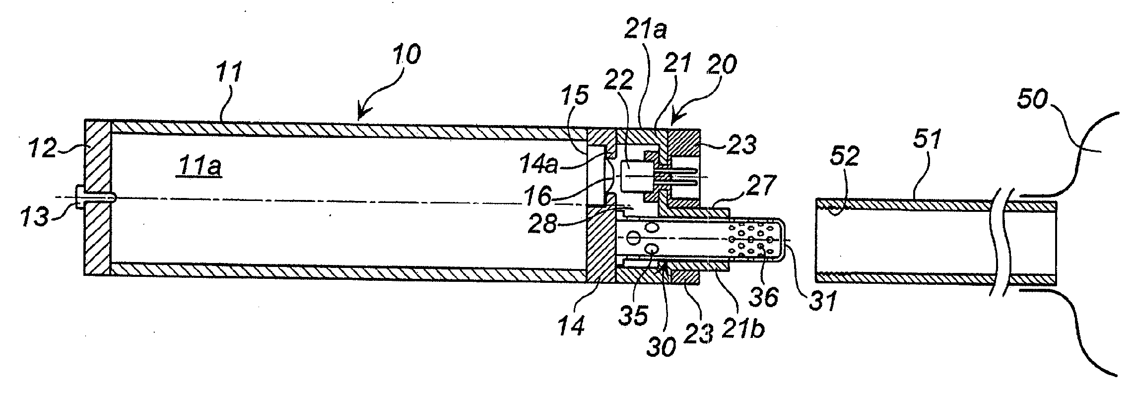
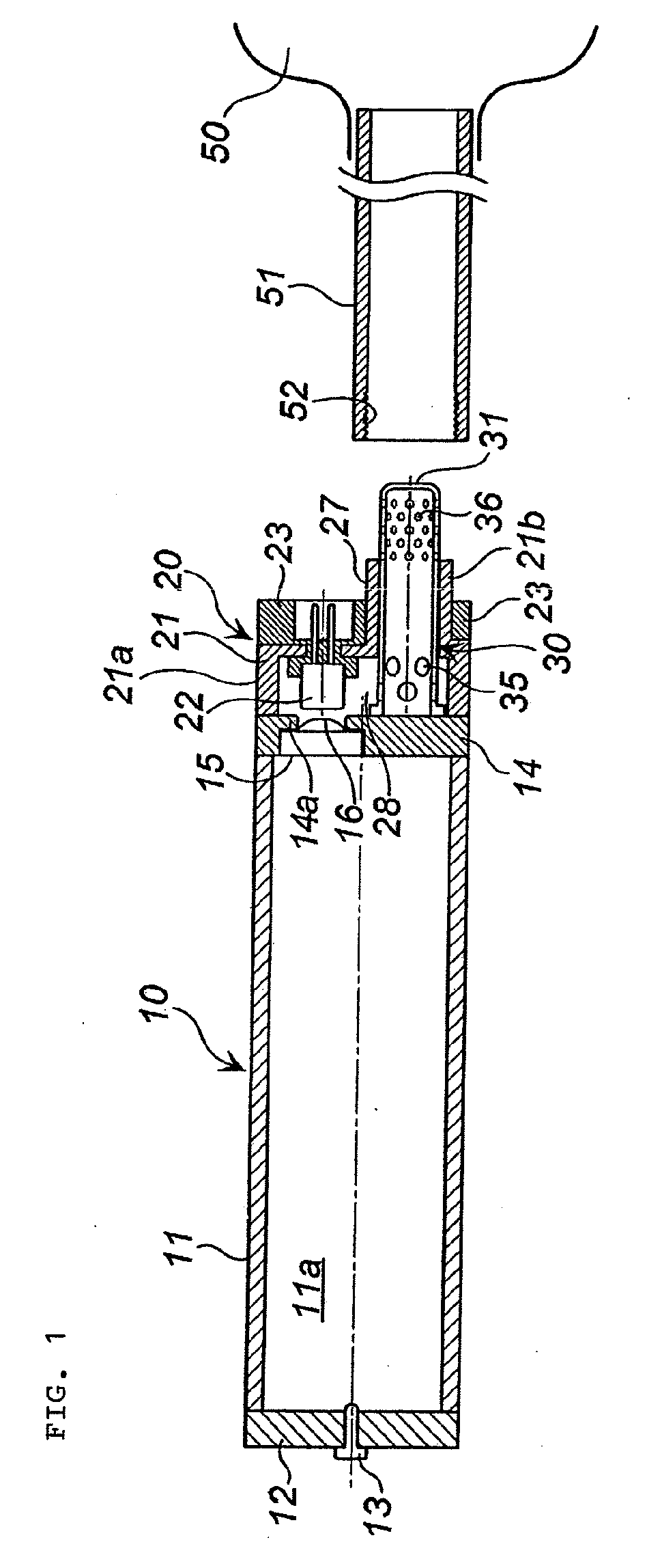
[0017]The present invention provides an inflator that is suitable for use in a restraining device of a vehicle, and in which a dimension in width direction is particularly reduced.

[0018]A housing in which one end is closed and the other end side is open is used as the tubular inflator housing, and the opening portion at the other end is closed by a closure. When a housing in which both ends are open is used as the inflator housing, the opening portions at the both ends may be closed by respective closures.

[0019]The tubular inflator housing preferably has a uniform diameter (a uniform width) from one end to the other end, but a housing that does not have a uniform diameter, such as a housing having a bulging central part, may be used instead. The width direction cross-sectional shape of the tubular inflator housing is preferably circular, but is not limited thereto, and may be elliptical or polygonal.

[0020]A gas such as argon or helium is charged at high pressure into the tubular inf...


PUM


Abstract

The invention relates to an inflator including:a tubular inflator housing in which an opening portion at one end is closed, an opening portion at the other end is closed by a closure and the interior is charged with a gas, an igniter assembly, attached to the closure side, and a tubular gas discharge port,the closure having an opening portion that serves as a gas passage in a part thereof, the opening portion being closed by a rupturable plate,the igniter assembly formed by integrating a part of a metallic igniter collar and an electric igniter with a resin,the igniter collar being fixed to the closure such that a space serving as a gas passage is formed between the igniter collar and the closure and an ignition portion of the electric igniter directly opposes the rupturable plate, andthe tubular gas discharge port including a plurality of gas discharge holes in a peripheral surface thereof, one end side of the tubular gas discharge port being welded and fixed to a part of the closure excluding the opening portion, a part of the peripheral surface of the tubular gas discharge port being supported by another part of the igniter collar, the other end side of the tubular gas discharge port projecting to the outside of the igniter collar.

Description

[0001]This nonprovisional application claims priority under 35 U.S.C. §119(a) on Patent Application No. 2007-254001 filed in Japan on 28 Sep. 2007, and 35 U.S.C. §119(e) on U.S. Provisional Application No. 60 / 976,975 filed on 2 Oct. 2007, which are incorporated by reference.BACKGROUND OF INVENTION[0002]1. Field of Invention[0003]The present invention relates to an inflator for use in a restraining device for a vehicle, such as an air bag apparatus.[0004]2. Description of Related Arts[0005]The attachment location of a stored gas type inflator, which is used in an air bag apparatus for a side collision protection or a curtain air bag apparatus, within a vehicle is restricted, and therefore demand for a reduction in size of this type of inflator is particularly high.[0006]In an inflator according to JP-A NO. 2003-104164, as shown in FIG. 1 thereof, a dimension in width direction is increased because a gas discharge port 40 is attached, and hence there is room for improvement in relatio...

Claims


Application Information

Patent Timeline
Patent Type & Authority Applications(United States)
IPC IPC(8): B60R21/26B60R21/268
CPCB60R21/274B60R21/268
Inventor YABUTA, MIKIOIWAI, YASUNORIUEDA, MASAYUKI
Owner DAICEL CHEM IND LTD
Why Eureka
Try Eureka