
Solar panel

a solar panel and solar energy technology, applied in the field of solar panels, can solve the problems of inconvenient maintenance, inconvenient installation, and inability to meet the needs of users, and achieve the effects of easy mass production, low maintenance, and efficient and inexpensive production

Inactive Publication Date: 2009-04-16
HELIOS PRODS
View PDF15 Cites 17 Cited by
  • Summary
  • Abstract
  • Description
  • Claims
  • Application Information

AI Technical Summary

Benefits of technology

[0007]It is another object of the present invention to provide a solar panel that utilizes the sun's rays to heat a liquid to be used for providing heat or hot water and that is efficient and inexpensive to produce.
[0008]It is a still further object of the present invention to provide a solar panel that utilizes the sun's rays to heat a liquid to be used for providing heat or hot water, that can be easily mass produced and which requires little or no maintenance.

Problems solved by technology

Many of the solar panels built during that period were manufactured in relatively small production series in an often unprofessional manner, which in time caused problems with water leakage amongst other things.
Consequently, they were heavy and cumbersome to handle and install, and were also undesirably expensive to construct and to use.
Non-rigid solar collectors constructed of plastic materials have also been proposed but none has proven successful.
While this may be an improvement on other prior art systems, it is still inefficient as much of the energy from the sun's rays is used merely to heat the darkened back panel and is not transferred to the liquid.

Method used


Image

  • Solar panel
  • Solar panel
  • Solar panel

Examples


Embodiment Construction

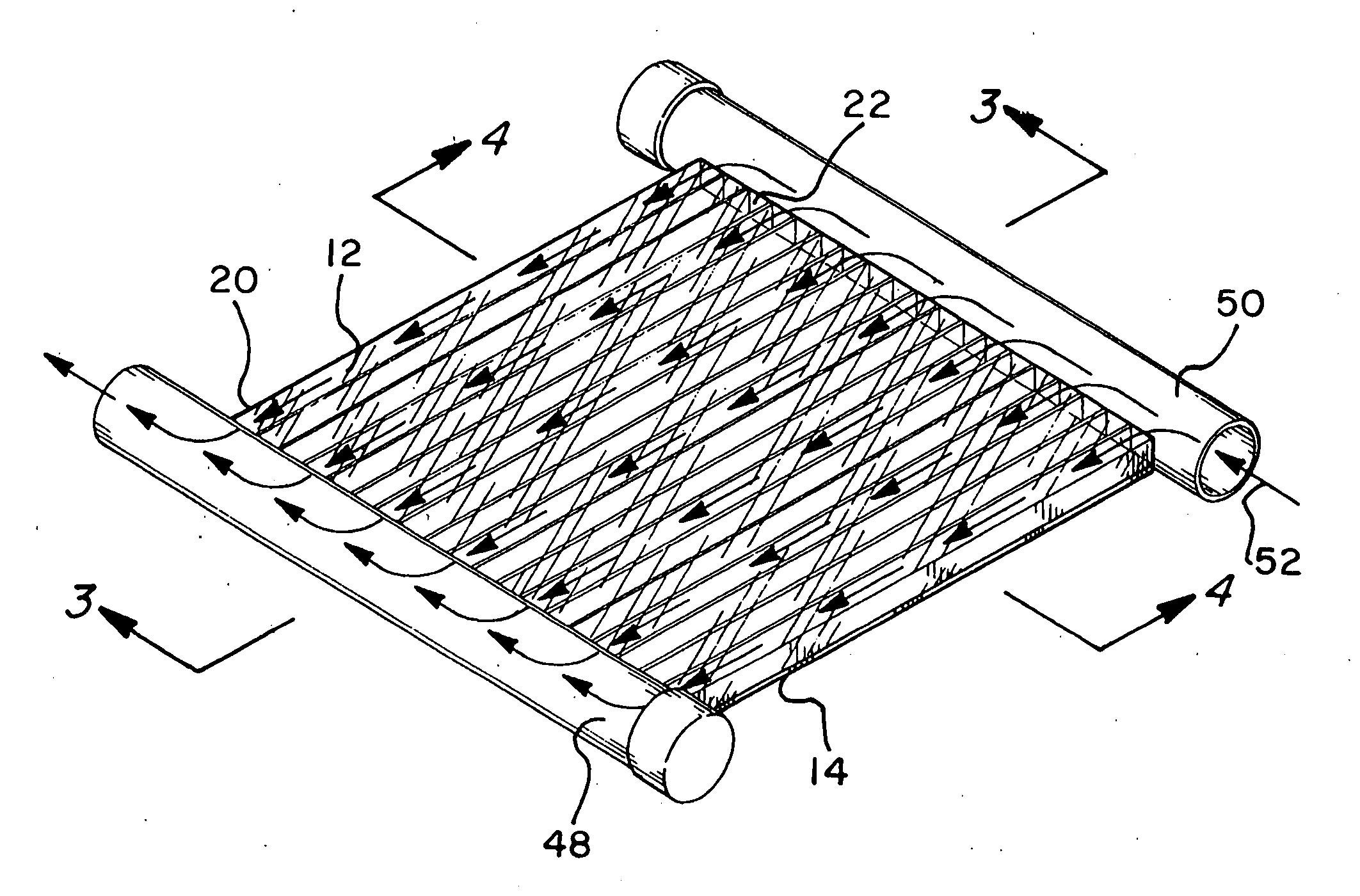
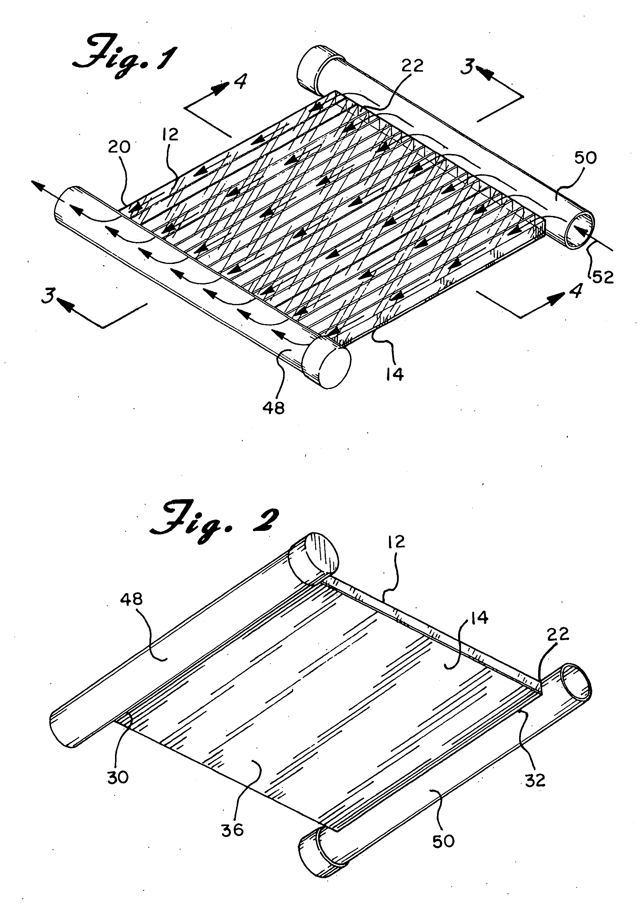
[0016]Referring now to the several drawings in detail wherein like reference numerals have been used throughout the various figures to designate like elements, there is shown in FIGS. 1 and 2 a solar panel of the type that utilizes the sun's rays to heat a liquid to be used for providing heat or hot water to a home or other building constructed in accordance with the principles of the present invention and designated generally as 10.

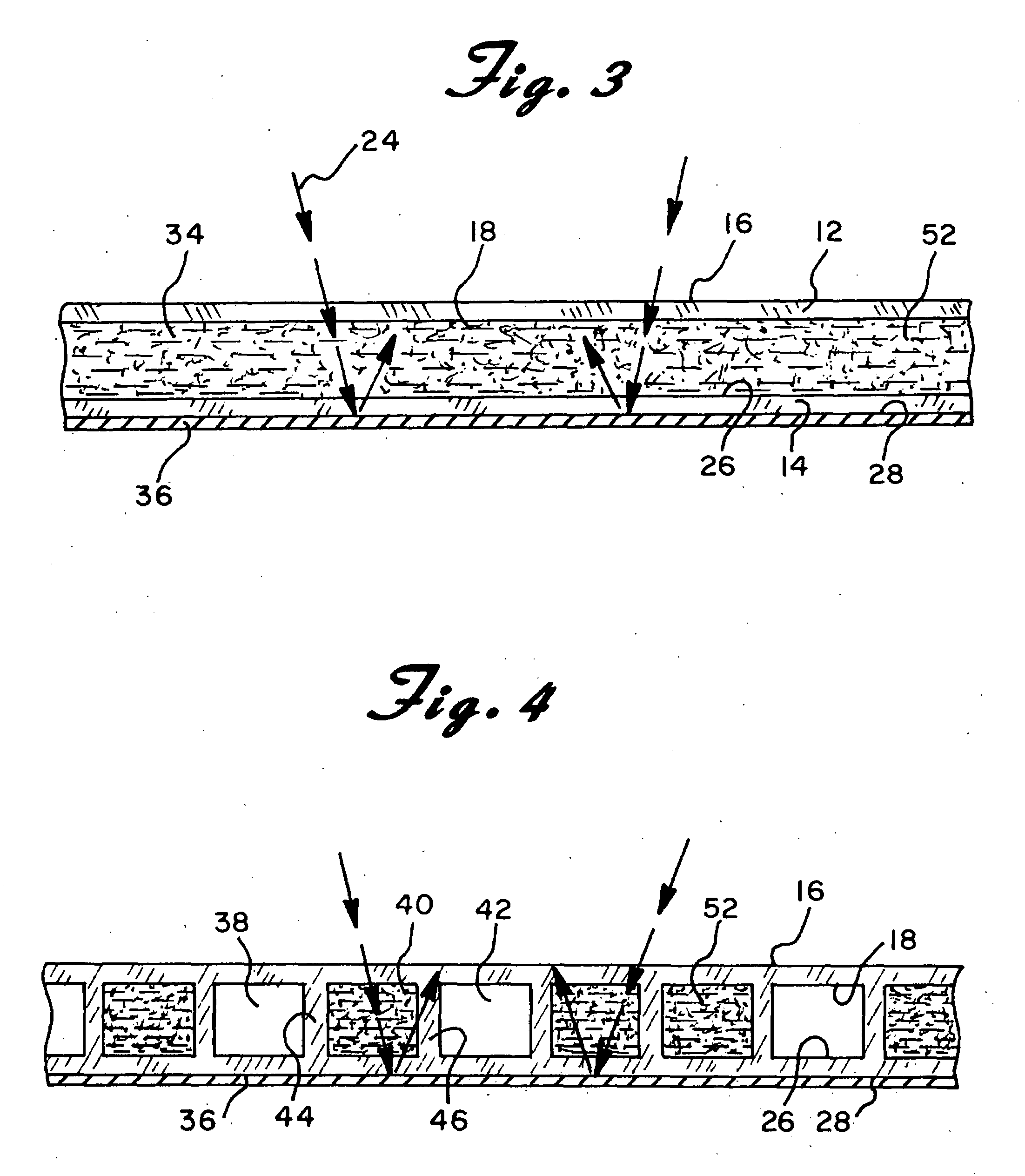
[0017]The solar panel 10 is comprised essentially of a front panel 12 and a rear panel 14. As shown most clearly in FIGS. 3 and 4, the front panel 12 has a front surface 16 and a back surface 18. It also has a left side edge 20 and a right side edge 22 as shown in FIG. 1. The front panel 12 is substantially transparent and is intended to face the sun so that they sun's rays 24 can pass therethrough substantially uninterrupted.

[0018]Similarly, the rear panel 14 includes a front surface 26, a back surface 28 and left and right side edges 30 and 32, respect...


PUM


Abstract

A solar panel that utilizes the sun's rays to heat a liquid to be used for providing heat or hot water includes front and rear parallel but spaced apart clear plastic panels. Each panel has a front surface, a back surface and left and right side edges. The front panel is intended to face the sun and is substantially transparent so that the sun's rays can pass therethrough. The rear panel has a reflective coating thereon wherein rays from the sun that pass through the front panel and through the space between the panels is reflective back toward the space. Located within the space between the panels are a plurality of conduits formed by a plurality of internal walls that extend between the front and rear panels and between the left and right side edges. Within the conduits is a darkened oily liquid that is heated by the incoming rays of the sun and by the rays reflected by the rear panel. In a preferred embodiment, the front and rear panels and the internal walls are extruded as a single unit.

Description

BACKGROUND OF THE INVENTION[0001]The present invention is directed toward a solar panel of the type that utilizes the sun's rays to heat a liquid to be used for providing heat or hot water to a home or other building.[0002]Solar panels, also known as solar heat collectors, of the type stated generally above have been known for many years. During the 1970s and 1980s a significant number of different solar panels were constructed and used as a result of the intensive energy debate which took place during this period with regard to alternative renewable sources of energy. Many of the solar panels built during that period were manufactured in relatively small production series in an often unprofessional manner, which in time caused problems with water leakage amongst other things.[0003]The early solar collectors were generally constructed of rigid materials such as glass and metal tubing. Consequently, they were heavy and cumbersome to handle and install, and were also undesirably expen...

Claims


Application Information

Patent Timeline
Patent Type & Authority Applications(United States)
IPC IPC(8): F24J2/20F24S23/70F24S10/50
CPCF24J2/202Y02E10/44Y02B10/20F24J2002/1071F24S10/502F24S2023/86
Inventor CRAMER, NEAL
Owner HELIOS PRODS
Learn More