Configurable linear light assembly and associated methods

Active Publication Date: 2014-11-06
LIGHTING SCI GROUP
View PDF1 Cites 1 Cited by
  • Summary
  • Abstract
  • Description
  • Claims
  • Application Information

AI Technical Summary

Benefits of technology

[0014]With the foregoing in mind, embodiments of the present invention are related to a linear light assembly used to produce a configurable beam of light emanating along a length of a luminaire. Embodiments of the present invention adv

Problems solved by technology

Current linear illumination device designs commonly consist of multiple members that often are complex to manufacture and assemble.
Design complexity may negatively impact both the manufacturability and the ease of installation of linear illumination devices.
More specifically, design complexity may complicate volume manufacturing of illumination products, which often involves collaboration between Original Equipment Manufacturers (OEMs) and Value Added Resellers (VARs).
Complexity of design in a component and/or a finished consumer good often results in error-prone and time-consuming assembly processes, and may make separation of distinct product manufacturing responsibilities among OEMs and VARs unworkably difficult.
A major design decision that may significantly impact illumination product cost and complexity is selection of the type of light sources to include in the product.
However, a number of design challenges and costs are associated with replacing traditional lamps with LED illumination devices.
These design challenges include thermal management, installation ease, and manufacturing cost control.
The complex designs of current LED-based linear illumination devices

Method used


Image

  • Configurable linear light assembly and associated methods
  • Configurable linear light assembly and associated methods
  • Configurable linear light assembly and associated methods

Examples


Embodiment Construction

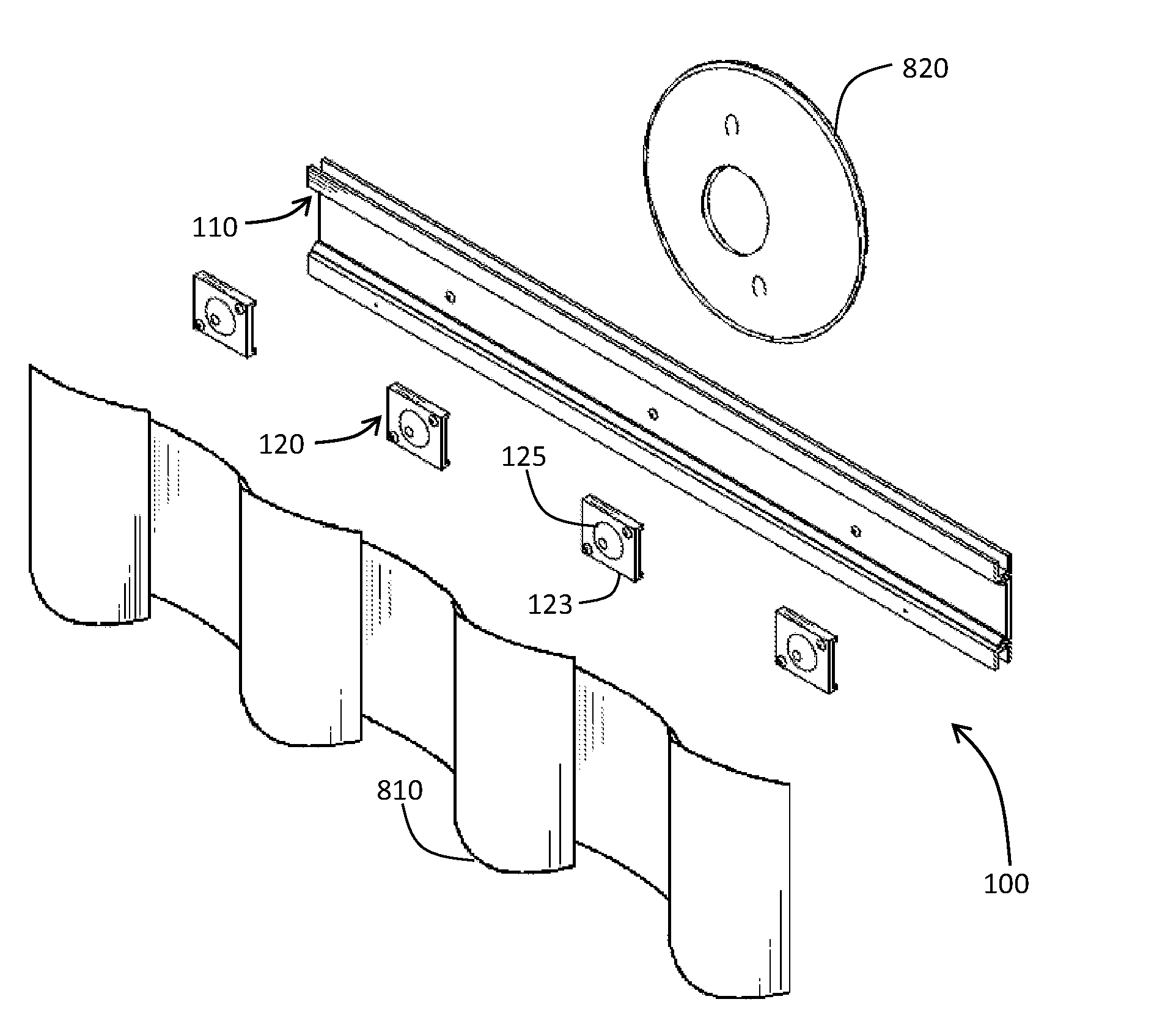
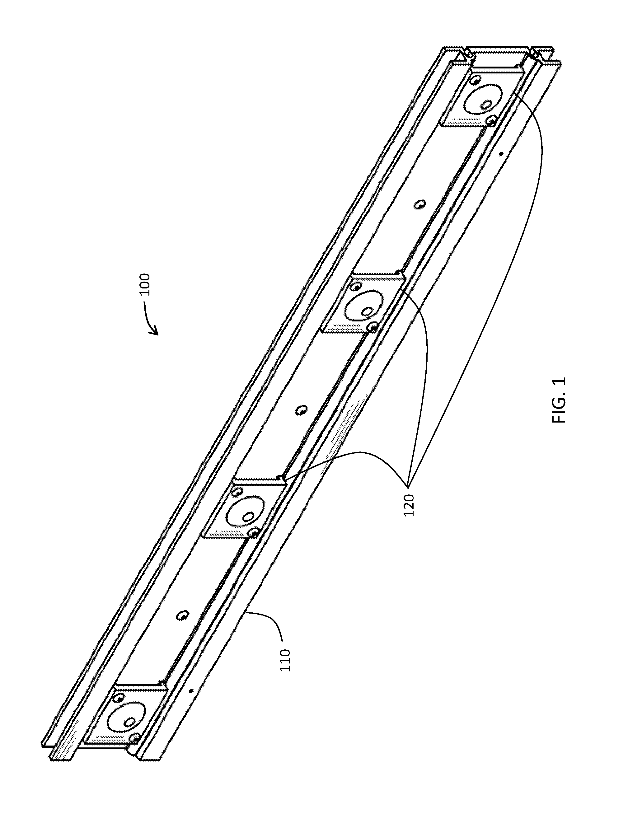
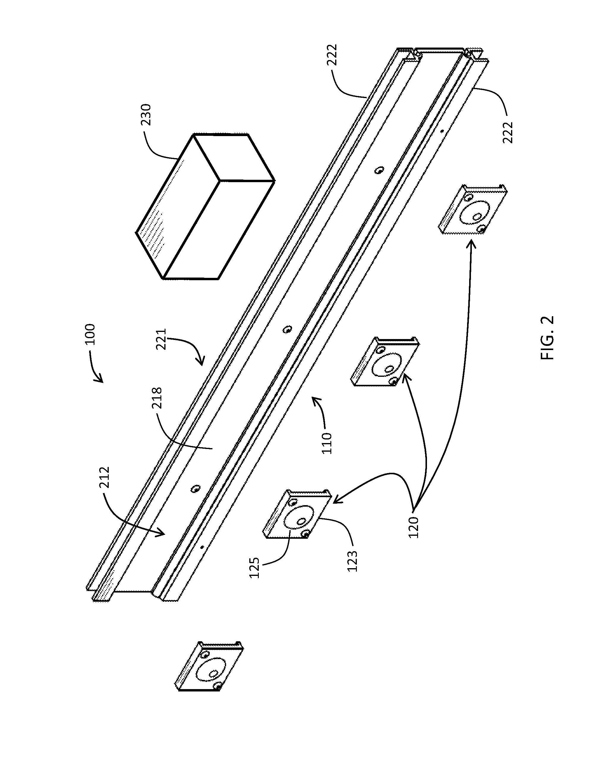
[0033]The present invention will now be described fully hereinafter with reference to the accompanying drawings, in which preferred embodiments of the invention are shown. This invention may, however, be embodied in many different forms and should not be construed as limited to the embodiments set forth herein. Rather, these embodiments are provided so that this disclosure will be thorough and complete, and will fully convey the scope of the invention to those skilled in the art. Those of ordinary skill in the art will realize that the following embodiments of the present invention are only illustrative and are not intended to be limiting in any way. Other embodiments of the present invention will readily suggest themselves to such skilled persons having the benefit of this disclosure.

[0034]Although the following detailed description contains many specifics for the purposes of illustration, anyone of ordinary skill in the art will appreciate that many variations and alterations to t...


PUM

PropertyMeasurementUnit
Poweraaaaaaaaaa
Heataaaaaaaaaa
Dissipation factoraaaaaaaaaa

Abstract

A linear light assembly having an elongate tray and a plurality of moveable lighting packages. The elongate tray may provide both mechanical support and thermal management for the plurality of moveable lighting packages. The elongate tray may comprise a medial channel portion with a planar track member and two opposing rim members projecting perpendicularly outward therefrom. Each flange portion may have a U-shaped cross-section. Each moveable package may comprise an assembly tray and an optical assembly having at least one light-emitting device (LED). Each moveable lighting package may be adjustably positioned along and independently removed from the front side of the track member of the elongate tray. Any segmentation of the elongate tray may be characterized by a heat dissipation rate not less than a combined heat generation rate of all moveable lighting packages carried by the segment. A method aspect includes installation of the linear light assembly.

Description

RELATED APPLICATIONS[0001]This application claims the benefit of U.S. Provisional Patent Application Ser. No. 61 / 643,310 filed on May 6, 2012 and titled Configurable Linear Light and Associated Methods, the entire contents of which are incorporated herein by reference.FIELD OF THE INVENTION[0002]The present invention relates to the field of illumination devices and, more specifically, to the field of light-emitting diode (LED)-based linear illumination devices, and associated methods.BACKGROUND OF THE INVENTION[0003]Linear-type illumination devices typically are characterized by multiple light sources mounted and spaced apart from one another along a length of an elongate substrate. Such illumination devices are often designed to present a low profile when installed flush to an existing surface, such as a wall.[0004]Current linear illumination device designs commonly consist of multiple members that often are complex to manufacture and assemble. For example, linear illumination devi...

Claims


Application Information

Patent Timeline
IPC IPC(8): F21V21/005F21V29/00
CPCF21V29/004F21V21/005F21S8/03F21V19/0045F21Y2113/00F21V29/767F21S4/28F21Y2103/10F21Y2115/10Y10T29/49002
Inventor MAXIK, FREDRIC S.WIDJAJA, ADDY S.OOSTDYK, MARK ANDREWSOLER, ROBERT R.BARTINE, DAVID E.
Owner LIGHTING SCI GROUP
Why Eureka
Try Eureka