
Systems and methods for using calibration profiles in valve actuators

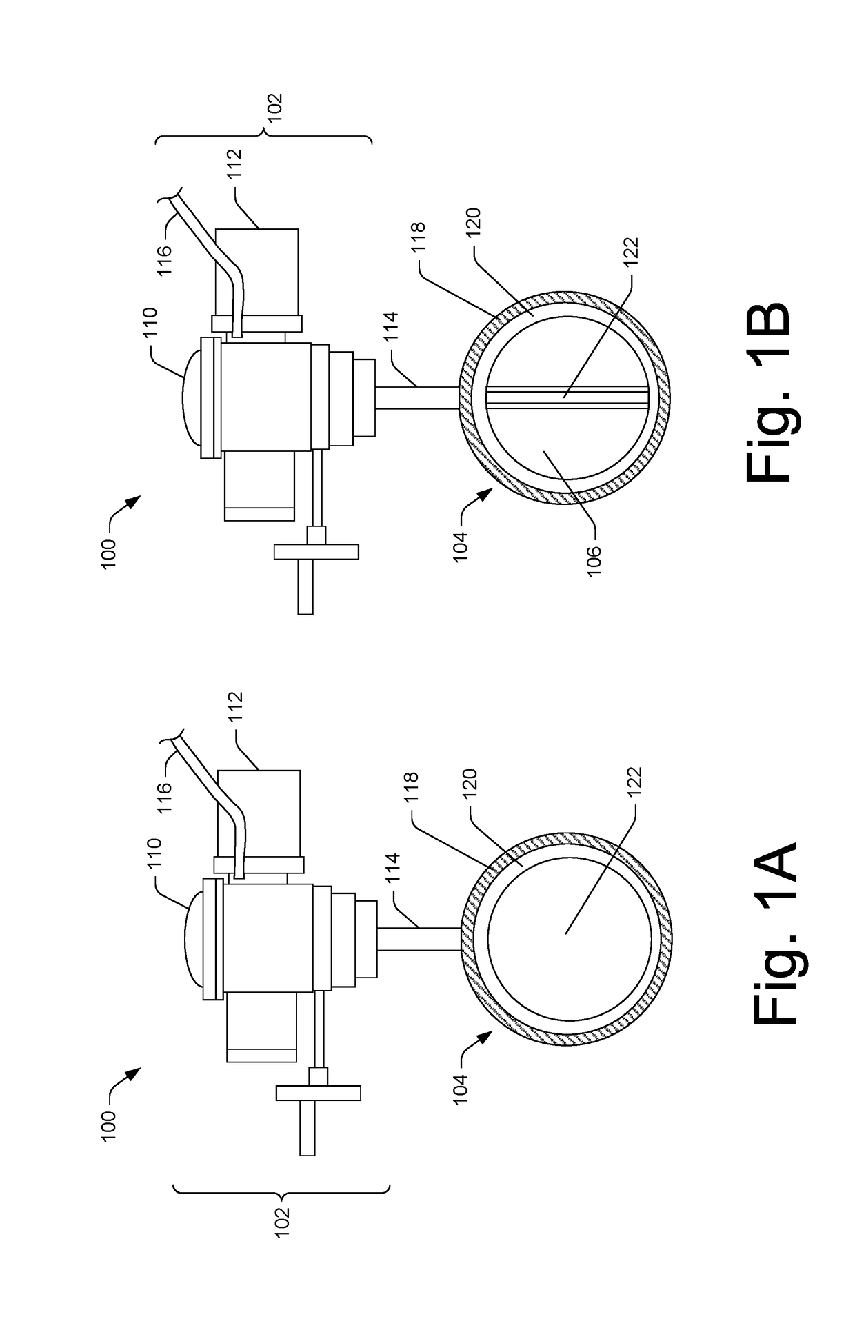
a technology of valve actuators and calibration profiles, which is applied in the direction of valve operating means/releasing devices, instruments, mechanical equipment, etc., can solve the problems of valves that are not frequently operated, valves may get stuck when the valve is infrequently operated, and the torque required to actuate may be significant, so as to facilitate preventative maintenance, prevent damage to valve components, and increase the safety of operators and other personnel

Active Publication Date: 2018-12-20
TRI TEC MFG
View PDF8 Cites 4 Cited by
  • Summary
  • Abstract
  • Description
  • Claims
  • Application Information

AI Technical Summary

Benefits of technology

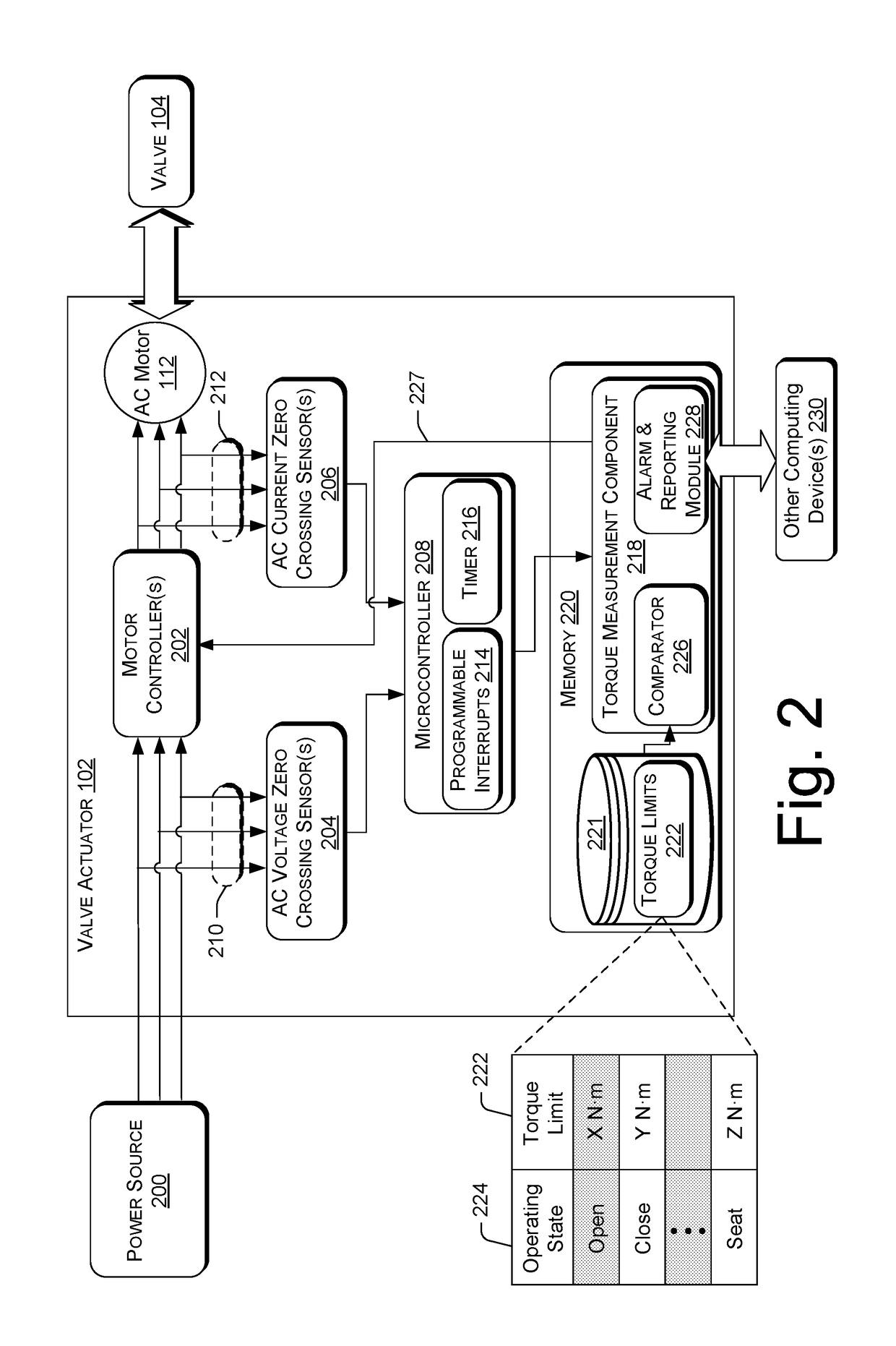
The patent describes a valve system with a feature that measures the torque of the valve, which is important for ensuring the valve is fully closed and secure. This helps prevent damage to components and increases safety for operators. The system uses a microcontroller with a timer to digitally determine the amount of torque produced by the motor, which simplifies the design and reduces costs compared to previous systems. Overall, the patent introduces a novel valve actuator that improves safety, prevents damage, and contributes to the overall technological process of closing a valve.

Problems solved by technology

A number of forces and pressures may act on the valve from the fluid in the passageway, and, depending on the environment in which a valve system is implemented, the amount of torque required to actuate the valve may be significant.
In some environments, such as valves that are implemented in a seawater system (e.g., a marine vessel), a valve may get stuck when the valve is infrequently operated.
For example, barnacles and other obstructions may form over time, which may affect how much torque is required to actuate the valve when it is necessary to do so.
For AC motors, one cannot simply measure the current drawn by the AC motor.
For instance, as the torque applied by the AC motor increases, the absolute value of the AC current may not change significantly, possibly making it difficult to derive torque from a simple measurement of AC current.
However, adding multiple mechanical-based sensors to a valve actuator can undesirably increase the weight and cost of the actuator.
However, conventional electrical sensors can be complex in design, making for a system that is relatively difficult and costly to manufacture.

Method used


Image

  • Systems and methods for using calibration profiles in valve actuators
  • Systems and methods for using calibration profiles in valve actuators
  • Systems and methods for using calibration profiles in valve actuators

Examples


example processes

[0049]The processes described in this disclosure may be implemented by the architectures described herein, or by other architectures. These processes are illustrated as a collection of blocks in a logical flow graph. Some of the blocks represent operations that can be implemented in hardware, software, or a combination thereof. In the context of software, the blocks represent computer-executable instructions stored on one or more computer-readable storage media that, when executed by one or more processors, perform the recited operations. Generally, computer-executable instructions include routines, programs, objects, components, data structures, and the like that perform particular functions or implement particular abstract data types. The order in which the operations are described is not intended to be construed as a limitation, and any number of the described blocks can be combined in any order or in parallel to implement the processes. It is understood that the following proces...


PUM

PropertyMeasurementUnit
AC voltageaaaaaaaaaa
AC currentaaaaaaaaaa
torqueaaaaaaaaaa

Abstract

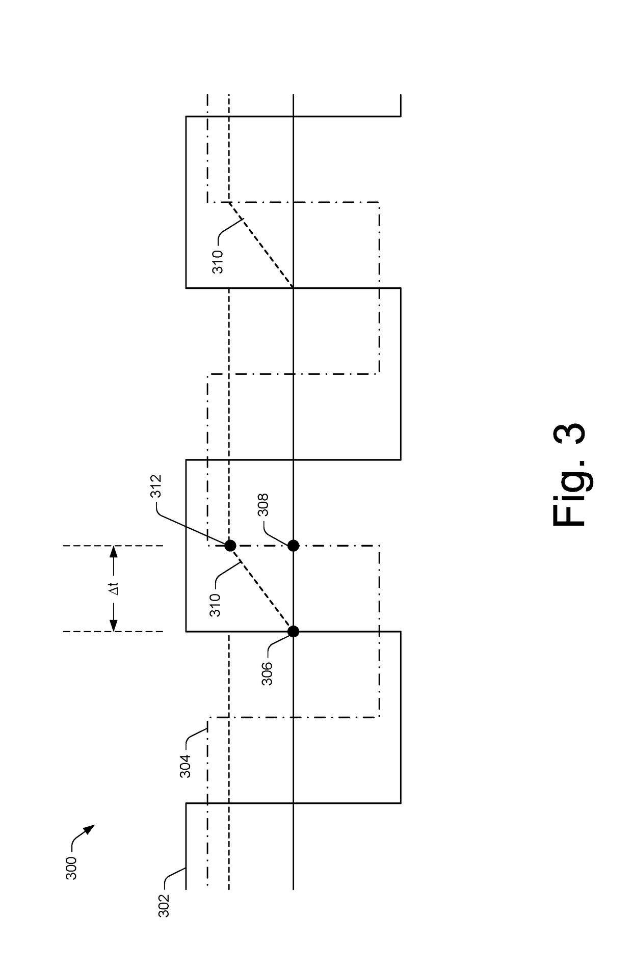
Disclosed is a valve actuator configured to determine, during operation of a valve by an alternating current (AC) motor of the valve actuator, an amount of torque produced by the AC motor. A process for measuring the amount of torque produced by the AC motor includes actuating a valve using the AC motor of the valve actuator, measuring, by a microcontroller of the valve actuator and during the actuating of the valve, a time interval between: (i) a first zero crossing of a waveform of AC voltage applied to the AC motor, and (ii) a second zero crossing of a waveform of AC current drawn by the AC motor, and determining, based on the time interval, an amount of torque produced by the AC motor during the actuating.

Description

BACKGROUND[0001]Valve actuators are configured to operate valves that regulate or control the flow of a fluid through a passageway by opening, closing, or partially obstructing the passageway. A number of forces and pressures may act on the valve from the fluid in the passageway, and, depending on the environment in which a valve system is implemented, the amount of torque required to actuate the valve may be significant. In some environments, such as valves that are implemented in a seawater system (e.g., a marine vessel), a valve may get stuck when the valve is infrequently operated. For example, barnacles and other obstructions may form over time, which may affect how much torque is required to actuate the valve when it is necessary to do so. Thus, in many instances, it is useful to measure and monitor the torque applied to the valve at any given time during operation of the valve.[0002]Automated valve actuators typically include an electric motor. Some valve actuators may includ...

Claims


Application Information

Patent Timeline
Patent Type & Authority Applications(United States)
IPC IPC(8): G01L3/10
CPCG01L3/109F16K31/04F16K31/046F16K37/0083
Inventor GILBERT, ROYCORDRAY, RICHARD LYNN
Owner TRI TEC MFG
Learn More