
Device for carrying out a distraction or a compression of vertebral bodies during spinal surgery

a technology for a distraction or a compression of vertebrae, applied in the field of devices for carrying out distractions or compression of vertebrae during spinal surgery, can solve the problems of complex production and use of known devices, and the adjacent vertebrae usually have to be moved away from one another (distraction) or towards one another, so as to achieve the effect of convenient application

Active Publication Date: 2018-07-05
SILONY MEDICAL INT
View PDF0 Cites 3 Cited by
  • Summary
  • Abstract
  • Description
  • Claims
  • Application Information

AI Technical Summary

Benefits of technology

The present invention aims to provide a device that is simpler and easier to use than existing devices, while still being economical to produce. Specifically, the device allows for the positioning of the first eccentric bearing part and / or the second counter bearing part by clamping them onto the relevant extension part. This can be achieved by selecting the inner diameter of the bearing part to be slightly smaller than the outer diameter of the extension part, and then using a slight widening to push the bearing part onto the extension part. This allows for easy placement with hand-applied forces, while ensuring that the bearing part stays in place.

Problems solved by technology

In modern spinal surgery, in particular in minimally invasive spinal surgery where sleeve-shaped extension parts of the bone anchors, referred to as extenders, are used, the problem is often that usually adjacent vertebral bodies have to be moved away from one another (distraction) or moved towards one another (compression).
The known devices are complex to produce and complicated to use.

Method used


Image

  • Device for carrying out a distraction or a compression of vertebral bodies during spinal surgery
  • Device for carrying out a distraction or a compression of vertebral bodies during spinal surgery
  • Device for carrying out a distraction or a compression of vertebral bodies during spinal surgery

Examples


Embodiment Construction

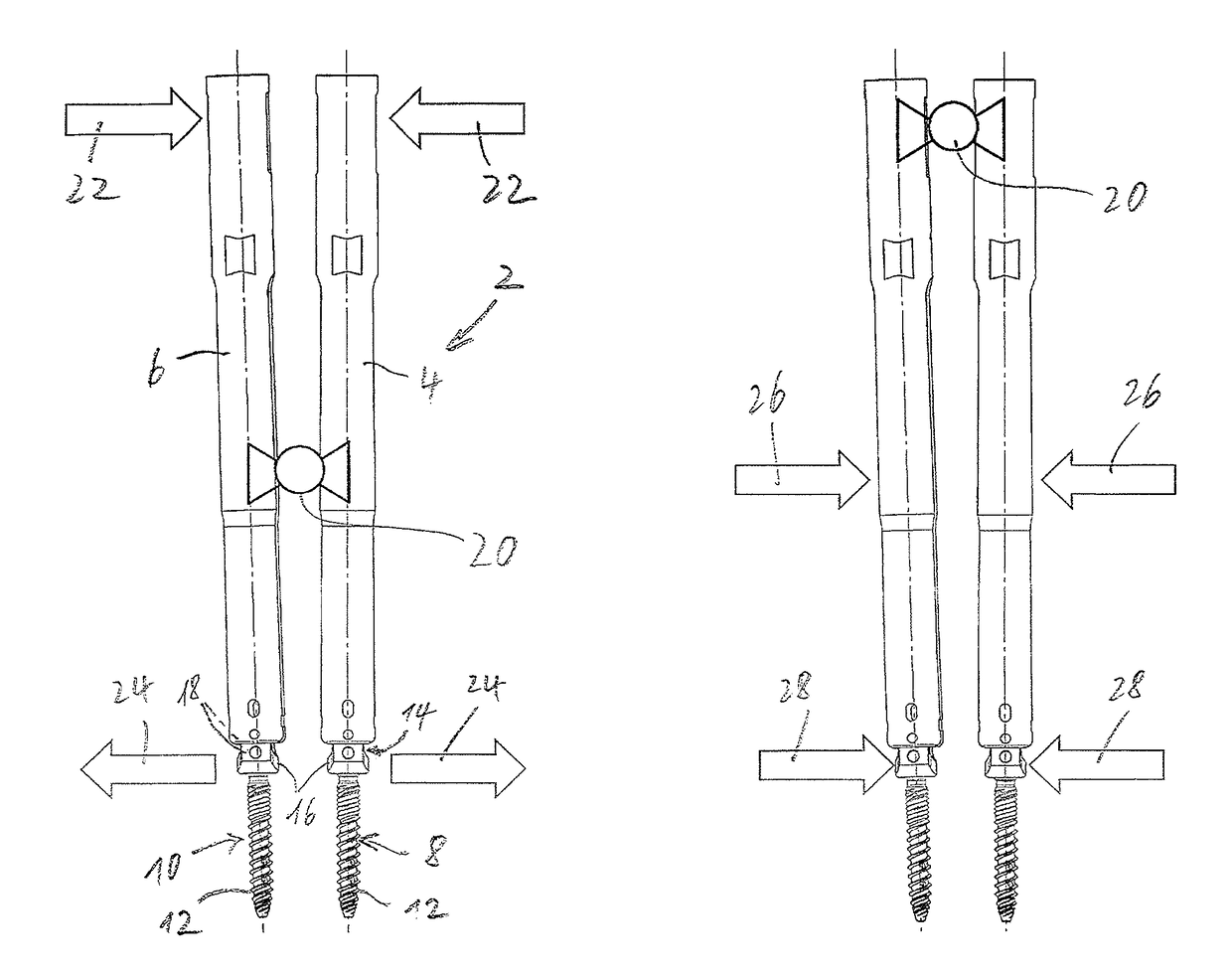
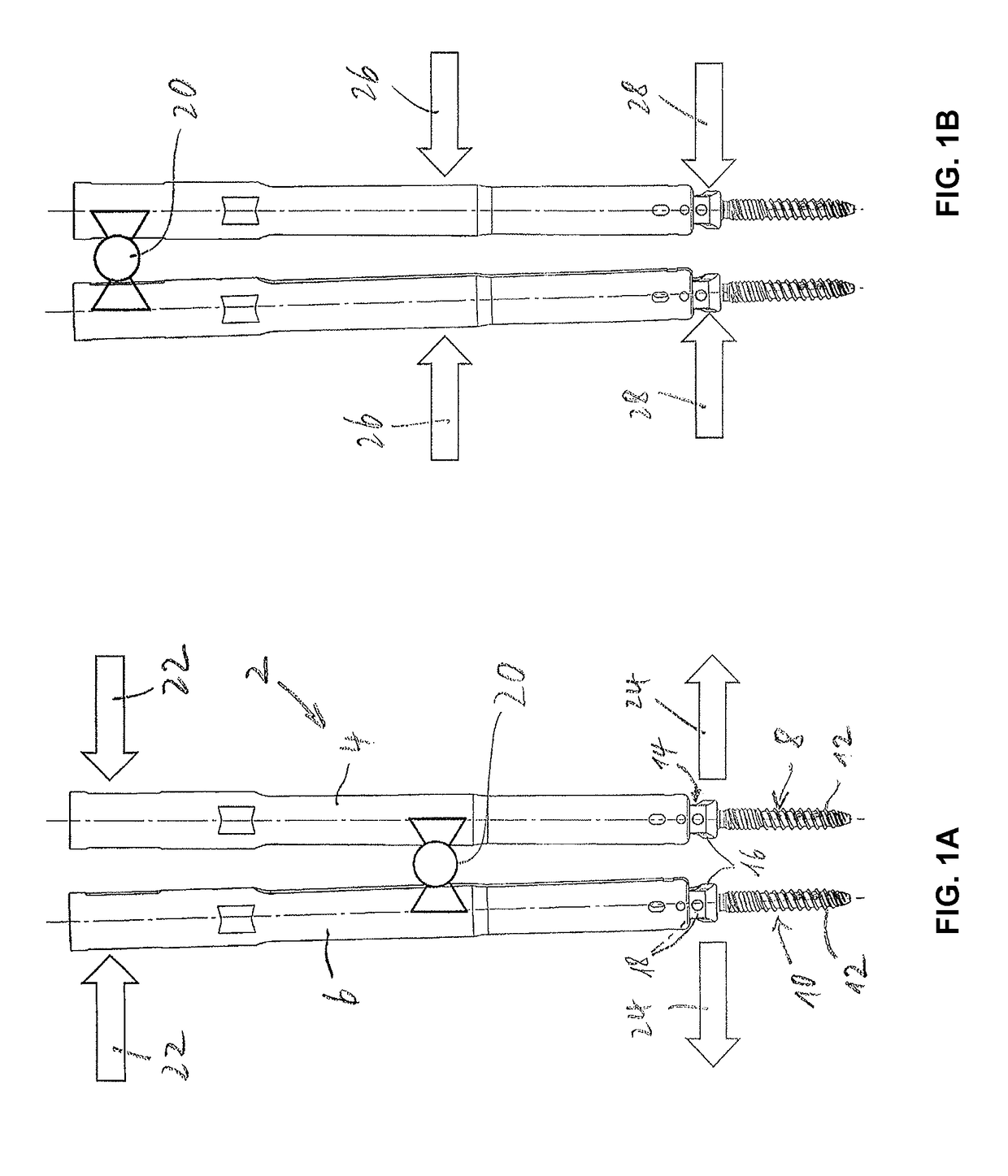
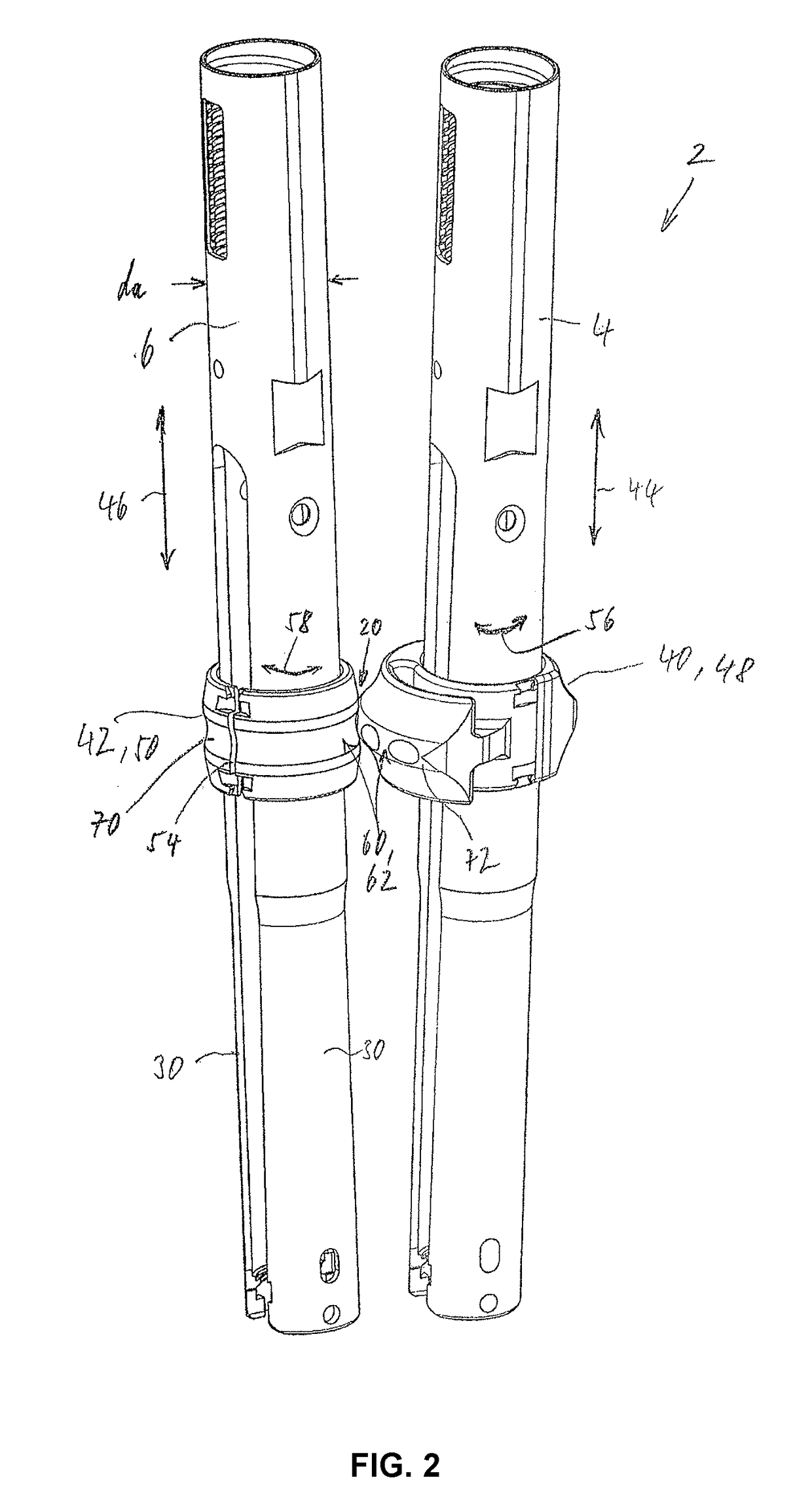
[0029]FIG. 1a schematically shows the conditions during a distraction and FIG. 1b shows said conditions during a compression of vertebral bodies during spinal surgery. A device according to the invention and denoted overall by reference sign 2 is shown schematically, said device comprising a first and a second sleeve-shaped extension part 4 and 6, respectively, shown by way of example in an upper region. Each extension part 4, 6 is connected to an associated bone anchor 8 and 10, respectively, in a detachable but rigid and rotationally fixed manner. The bone anchor 8, 10 is, by way of example and preferably, an osteosynthesis device, the bone anchor 8, 10 in each case comprising a threaded shank 12 to be screwed into a vertebral body, and a clevis 16 that is U-shaped in a side view, comprises a receiving opening 14 for a correction element, in particular a correction rod, and comprises two limbs 18. In this case, the relevant screw shank 12 is either formed rigidly, in particular in...


PUM


Abstract

Disclosed is a device for carrying out a distraction and / or a compression of vertebral bodies during spinal surgery, said device comprising a first and a second sleeve-shaped extension part, each part having a longitudinal direction and each of which parts can be secured on a bone anchor in a detachable but rigid and rotationally fixed manner. The device is characterised by a first eccentric bearing part and a second counter bearing part which parts can be positioned on the first and on the second extension part respectively in corresponding positions, and in that, at least the eccentric bearing part can be rotated relative to the first extension part about the longitudinal direction of said extension part, such that due to the eccentricity, the first bearing part can be brought into contact with the second counter bearing part and thus a bearing position is formed for forming a pivot joint between the two extension parts in order to perform the distraction or compression.

Description

[0001]The invention relates to a device for carrying out a distraction or a compression of vertebral bodies during in particular minimally invasive spinal surgery, said device comprising a first and a second extension part, which parts are in particular sleeve-shaped, at least in portions, each part having a longitudinal direction and each of which parts can be secured on a bone anchor in a detachable but rigid and rotationally fixed manner, the bone anchors in each case being intended to be inserted or being already inserted into one of the vertebral bodies to be treated.[0002]In modern spinal surgery, in particular in minimally invasive spinal surgery where sleeve-shaped extension parts of the bone anchors, referred to as extenders, are used, the problem is often that usually adjacent vertebral bodies have to be moved away from one another (distraction) or moved towards one another (compression). The new position can then be fixed by means of osteosynthesis devices, using correcti...

Claims


Application Information

Patent Timeline
IPC IPC(8): A61B17/70
CPCA61B17/708A61B17/7002A61B17/7076A61B17/7077A61B17/7079
Inventor OHNMACHT, TIMOHEUER, FRANK
Owner SILONY MEDICAL INT
Learn More