Extension device and tripod

Active Publication Date: 2009-04-16
VELBON
View PDF7 Cites 26 Cited by
  • Summary
  • Abstract
  • Description
  • Claims
  • Application Information

AI Technical Summary

Benefits of technology

[0013]According to the present invention, since it is not necessary to form a fall-out stopping inner projection portion at the second tubular member and a fal

Problems solved by technology

However, since, with the above-described configuration, it is necessary to form the fall-out stopping inner projection portion 1a at the lower end part of the upside tubular membe

Method used


Image

  • Extension device and tripod
  • Extension device and tripod
  • Extension device and tripod

Examples


Embodiment Construction

[0027]A description is given of an embodiment of the present invention with reference to the drawings.

[0028]In FIG. 3, reference numeral 10 denotes a tripod that is provided with a base portion 11. Extension devices 12 that are three long leg devices so as to extend and contract along the lengthwise direction are rotatably attached to the base portion 11. The respective extension devices 12 are composed of a multiple-stage type, for example, a three-stage type, and each of which has the same configuration. Also, a panhead 13 to which a camera, etc., is attached is mounted on the base portion 11. In addition, the following description is given based on the assumption that the extension direction (that is, the extension and contraction direction) of the extension devices 12 is an up and down direction.

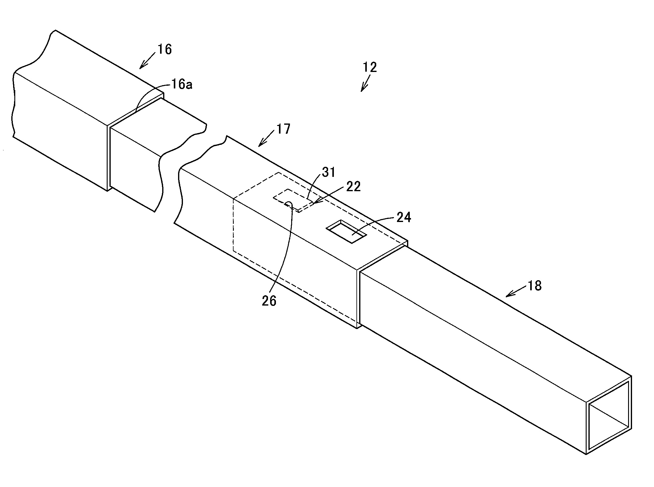
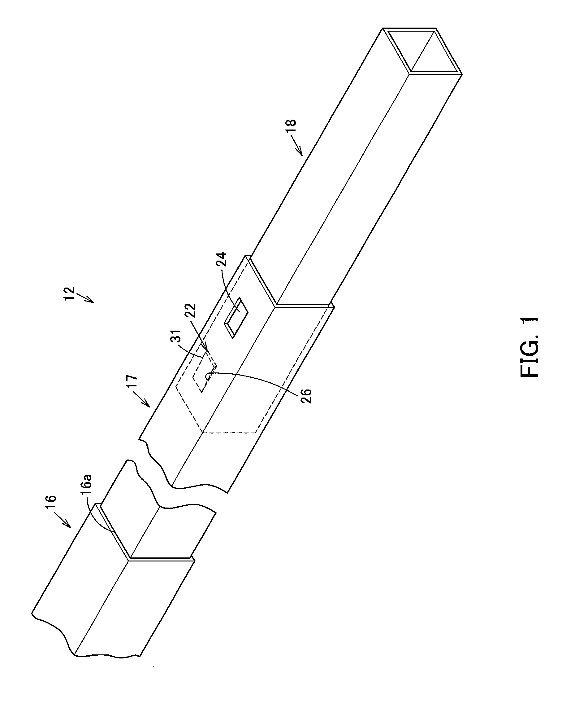
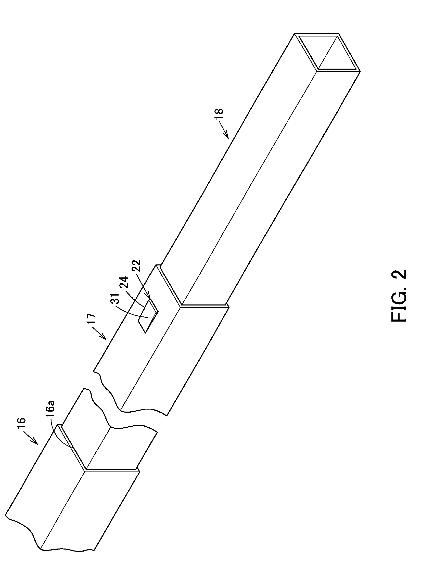
[0029]As shown in FIG. 1, FIG. 2, and FIG. 4 through FIG. 11, the extension device 12 is provided with a plurality of cylindrical tubular members, for example, three tubular members 16, ...


PUM


Abstract

An extension device includes the first tubular member, the second tubular member movably inserted into the first tubular member, and the third tubular member movably inserted into the second tubular member and a regulating device that regulates movement of the third tubular member with respect to the second tubular member. The regulating device includes a regulating member protruding from the inner hole portion to the outside of the third tubular member band is brought in the outer hole portion, and a pressing member for pressing the regulating member in the protruding direction.

Description

[0001]This is a U.S. national phase application under 35 U.S.C. § 371 of International Patent Application No. PCT / JP2008 / 054923 filed Mar. 18, 2008, and claims the benefit of Japanese Application No. 2007-070475, filed Mar. 19, 2007. The International Application has not been published at the time of this filing. The contents of both are incorporated herein in their entirety.TECHNICAL FIELD[0002]The present invention relates to an extension device and a tripod for which advantageous productivity is secured and production costs can be reduced.BACKGROUND ART[0003]Conventionally, for example, extension devices shown in FIG. 12 and FIG. 13 have been known as an extension device for a tripod leg apparatus (For example, refer to [online] Velbon Kabushiki Kaisha (retrieved on Feb. 28, 2007), Internet <URL: http: / / www.velbon.com / jp / catalog / classic / t100.html>.[0004]An extension device shown in FIG. 12 and FIG. 13 is provided with a cylindrical upside tubular member 1 having an inner pr...

Claims


Application Information

Patent Timeline
IPC IPC(8): F16M11/02F16M11/26
CPCF16B7/042F16M11/32F16M11/126Y10T403/32483F16M13/00F16M2200/028Y10T403/32467F16M11/22
Inventor NAKATANI, KOICHIRO
Owner VELBON
Why Eureka
Try Eureka