
Means for mounting a portable satellite antenna on a vehicle

a satellite antenna and portable technology, applied in the direction of antennas, antenna details, antenna adaptation in movable bodies, etc., can solve the problems of incorrect elevation setting of the antenna, satellite antenna not being plucked, and not always being perfectly positioned on the vehicle, so as to achieve quick and easy installation and quick and easy plumbing of the supporting tube

Inactive Publication Date: 2009-04-16
KRAJICEK WILLIAM F
View PDF14 Cites 28 Cited by
  • Summary
  • Abstract
  • Description
  • Claims
  • Application Information

AI Technical Summary

Benefits of technology

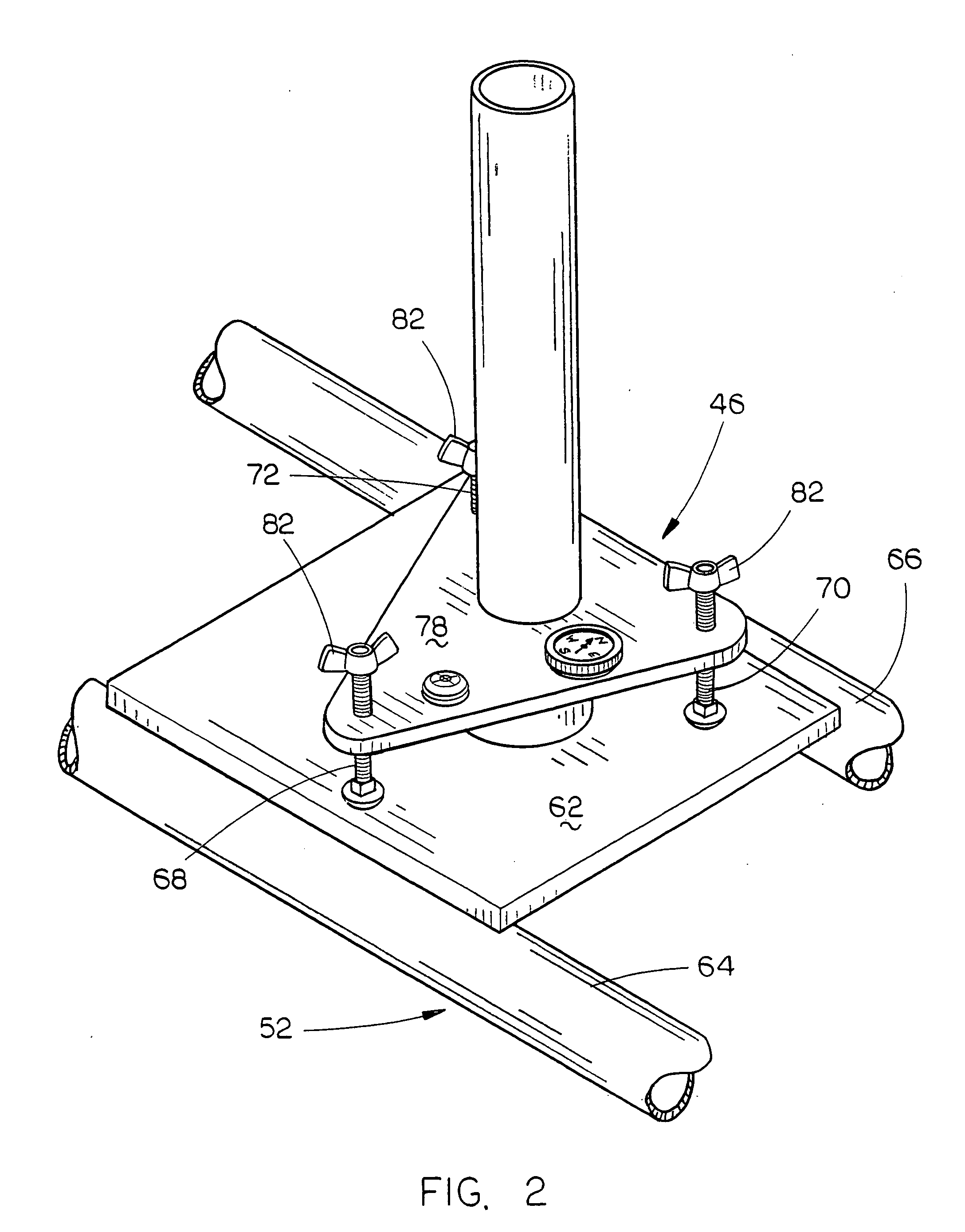
[0010]A further object of the invention is to provide a mounting means for a portable satellite antenna including means for quickly and easily plumbing a supporting tube so that the mast of the antenna when placed thereon will be plumb.
[0011]Yet another object of the invention is to provide a means for mounting a portable satellite antenna on a vehicle which is quickly and easily mounted thereon.

Problems solved by technology

Many ways of mounting a portable satellite antenna have been previously provided but it is not believed that any of the previous devices enable a portable satellite antenna to be quickly and easily mounted on the roof rack of a vehicle or on the box of a pick-up truck.
In any device for mounting a portable satellite antenna on a vehicle, a problem encountered is that the vehicle will not always be perfectly level with the result being that the mast of the satellite antenna will not be plumb.
If it is not plumb, the elevation setting of the antenna will be incorrect.
Further, the problem encountered in the mounting of a portable satellite antenna on a vehicle is that the antenna does not interfere with the normal use of the vehicle which is extremely important when the vehicle is being used for tailgating functions or the like.
A further problem encountered in the mounting of a portable satellite antenna on a vehicle is that the vehicle must not interfere with the reception of the satellite signal by the antenna.

Method used


Image

  • Means for mounting a portable satellite antenna on a vehicle
  • Means for mounting a portable satellite antenna on a vehicle
  • Means for mounting a portable satellite antenna on a vehicle

Examples


Embodiment Construction

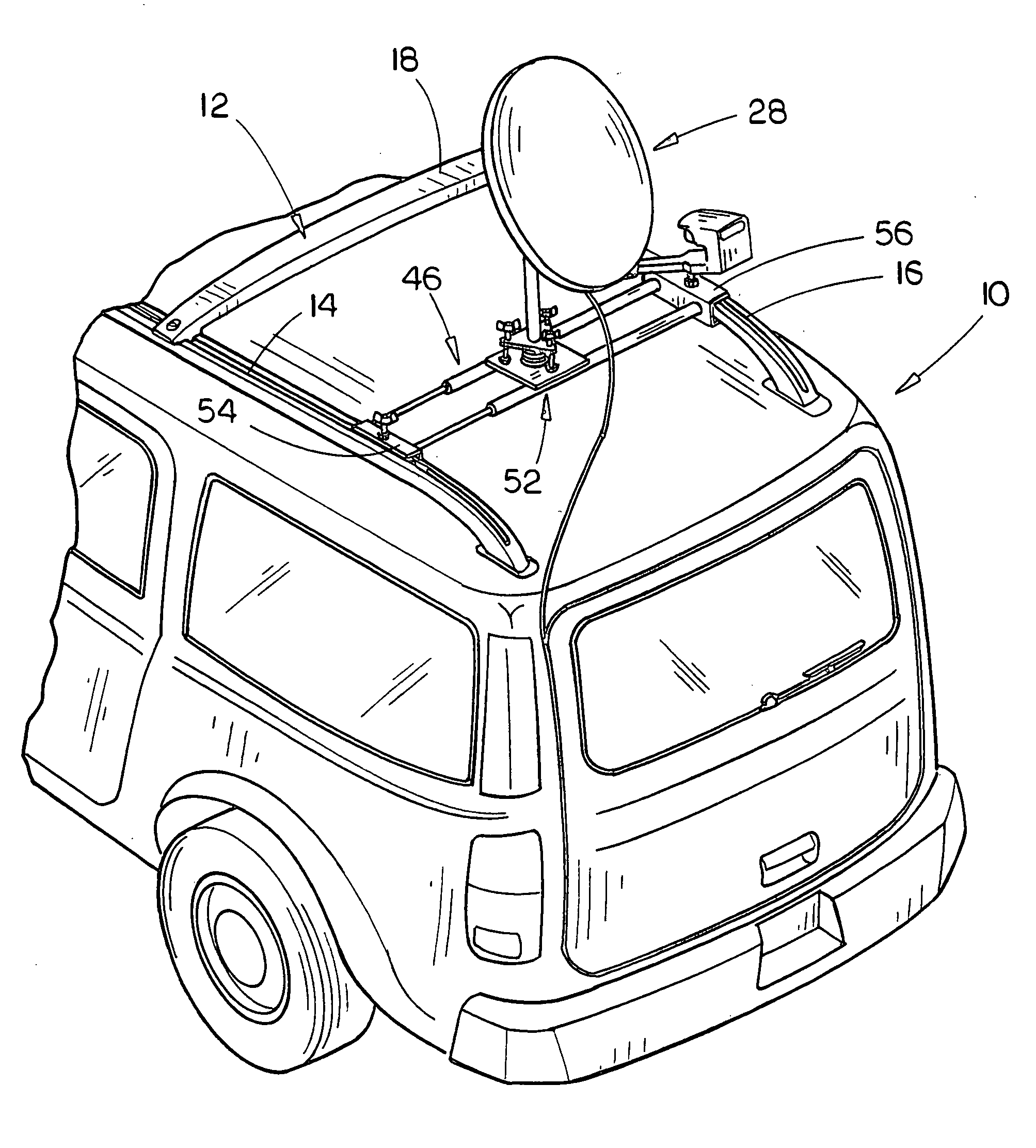
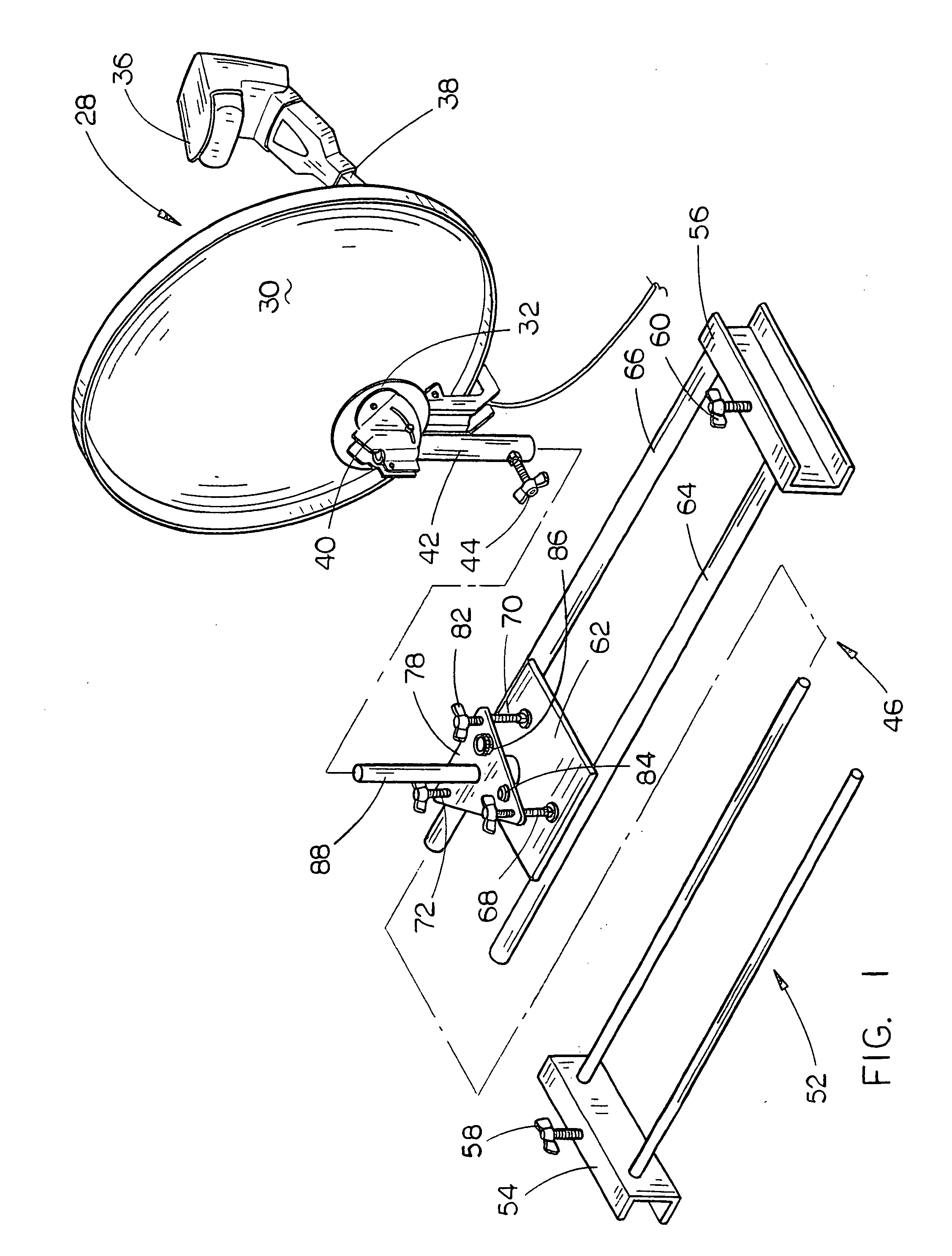
[0025]In the drawings, the numeral 10 refers to vehicle such a van, SUV or the like which has a roof rack 12 mounted thereon. Roof rack 12 normally includes a pair of longitudinally and horizontally spaced apart side rack members or rails 14 and 16 and which has two or more transversely extending rack members or rails 18 and 20 slidably adjustably mounted on the rails 14 and 16.

[0026]In FIGS. 6 and 7, the numeral 22 refers to a pick-up truck having a box or bed which includes upstanding side walls 24 and 26 having upper ends.

[0027]In the drawings, the numeral 28 refers to a conventional satellite antenna including a reflector or dish 30, reflector support 32, LNB horn 36, and an LNB support arm 38 extending therefrom to the mounting bracket assembly 40 of the antenna 28. The mounting bracket assembly 40 includes conventional means for adjusting the elevation of the reflector 30 and means for adjusting the skew of the reflector 30. Normally, a mast extends from the mounting bracket a...


PUM


Abstract

Several different embodiments are illustrated for attaching, supporting or mounting a portable satellite antenna on a vehicle or supported by the vehicle. In two of the embodiments, the satellite antenna is secured to the roof rack of the vehicle. In a third embodiment, the satellite antenna is secured to the upper ends of the sides of a pickup truck. Alternative methods for mounting or supporting the portable satellite antenna are also disclosed.

Description

BACKGROUND OF THE INVENTION[0001]1. Field of the Invention[0002]This invention relates to a means for mounting a portable satellite antenna on a vehicle and more particularly to a means for mounting a portable satellite antenna on the roof rack of a vehicle or on the sides of the box of a pick-up truck. This invention further relates to an antenna supporting structure which is stabilized by a tire of a vehicle.[0003]2. Description of the Related Art[0004]Many ways of mounting a portable satellite antenna have been previously provided but it is not believed that any of the previous devices enable a portable satellite antenna to be quickly and easily mounted on the roof rack of a vehicle or on the box of a pick-up truck. In any device for mounting a portable satellite antenna on a vehicle, a problem encountered is that the vehicle will not always be perfectly level with the result being that the mast of the satellite antenna will not be plumb. It is important to be sure that the mast ...

Claims


Application Information

Patent Timeline
Patent Type & Authority Applications(United States)
IPC IPC(8): H01Q1/32H01Q1/12
CPCH01Q1/3275H01Q1/1207
Inventor KRAJICEK, WILLIAM F.
Owner KRAJICEK WILLIAM F
Learn More