Reliable contact and safe system and method for providing power to an electronic device

a technology of reliable contact and safe system, applied in the direction of emergency power supply arrangement, coupling device connection, conductive layer on the insulating support, etc., can solve the problems of not making the power cord unit compatible with the electronic devices of other manufacturers, other types of electronic devices, etc., and the battery connector made for one type of device typically will not fit into the battery power receptacle made for another type of devi

Active Publication Date: 2009-04-16
FLI CHARGE LLC
View PDF19 Cites 29 Cited by
  • Summary
  • Abstract
  • Description
  • Claims
  • Application Information

AI Technical Summary

Benefits of technology

[0010]An embodiment of the present invention may comprise an electrical apparatus, comprising: a power delivery surface that comprises at least a part of a support surface, the power delivery surface being connected to an electrical power source, the power delivery surface being capable of supplying electrical power, and the power delivery surface having a plurality of pads, wherein some of the pads are at a first voltage level and others of the pads are at a second voltage level; an electrical device, which is supplied electricity and is positionable in any location on

Problems solved by technology

Manufacturers, however, generally make their own model of electronic device and do not make their power cord unit compatible with the electronic devices of other manufacturers, or with other types of electronic devices.
As a result, a battery connector made by one manufacturer will typically not fit into the battery power receptacle made by another manufacturer.
Further, a battery connector made for one type of device typically will not fit into the battery power receptacle made for another type of device.
This may be troublesome for the consumer because he or she has to buy a compatible power cord unit for their particular electronic device.
Since people tend to switch devices often, it is inconvenient and expensive for them to also have to switch power cord units.
Further, power cord units that are no longer useful are often discarded which leads to waste.
Also, people generally own a number of different types of electronic devices and owning a power cord unit for each one is inconvenient because the consumer must deal with a large quantity of power cord units and the tangle of power cords the situation creates.

Method used


Image

  • Reliable contact and safe system and method for providing power to an electronic device
  • Reliable contact and safe system and method for providing power to an electronic device
  • Reliable contact and safe system and method for providing power to an electronic device

Examples


Embodiment Construction

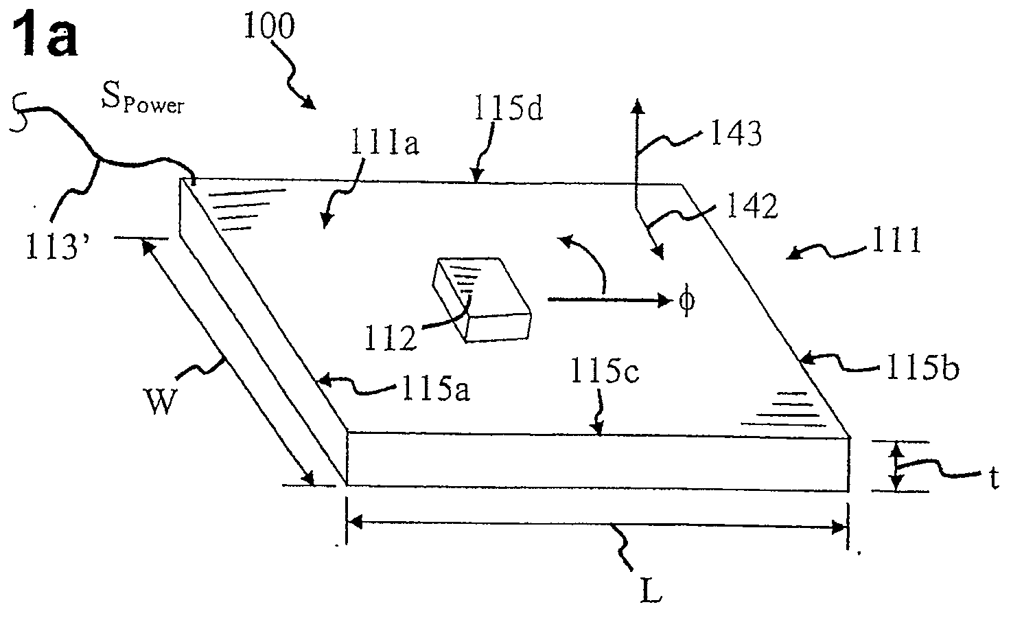
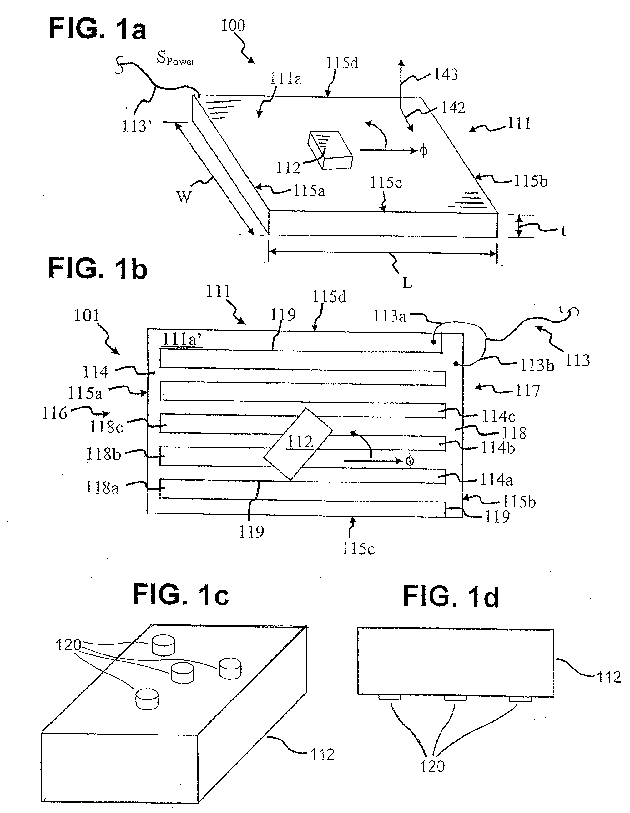
[0038]FIG. 1a is a perspective view of a power delivery system 100, in accordance with the invention, for providing power to an electrical or electronic device 112 with a power delivery surface 111a. System 100 has many different embodiments that provide the features discussed herein and as well as other features. Several embodiments are discussed in co-pending U.S. patent application Ser. No. 11 / 670,842 filed on Feb. 2, 2007, co-pending U.S. patent application Ser. No. 11 / 672,010 filed Feb. 6, 2007, and co-pending U.S. patent application Ser. No. 11 / 682,309 filed Mar. 5, 2007. Power delivery system 100 can power more than one electronic device made by the same or different manufacturers. It can also power different types of electronic devices. This reduces the need for the consumer to have a power cord unit for each electronic device they use. Electronic device 112 can be of many different types, such as a toys, game devices, cell phone, laptop computer, camera, personal digital as...


PUM


Abstract

An electronic system which includes a power delivery surface that delivers electrical power to an electrical or electronic device. The power delivery surface may be powered by any electrical power source, including, but not limited to: wall electrical outlet, solar power system, battery, vehicle cigarette lighter system, direct connection to electrical generator device, and any other electrical power source. The power delivery surface delivers power to the electronic device wirelessly. The power delivery surface may deliver power via a plurality of contacts on the electrical device conducting electricity from the power delivery surface. The electrical device may be mobile device. Each contact may be shaped to improve power delivery reliability. The power delivery surface may further include circuitry to protect against accidental electrocutions.

Description

CROSS-REFERENCES TO RELATED APPLICATIONS[0001]This application claims the benefit of U.S. Provisional Application No. 60 / 797,140, filed May 3, 2006, all of which is incorporated herein by reference, and it is a continuation-in-part of U.S. patent application Ser. No. 11 / 670,842, filed Feb. 2, 2007, U.S. patent application Ser. No. 11 / 672,010, filed on Feb. 6, 2007 which additionally claims the benefit of U.S. Provisional Application No. 60 / 776,332, filed Feb. 24, 2006, and U.S. patent application Ser. No. 11 / 682,309, filed on Mar. 5, 2007 which additionally claims the benefit of U.S. Provisional Application No. 60 / 778,761, filed Mar. 3, 2007, U.S. Provisional Application No. 60 / 781,456, filed Mar. 10, 2007, which are a divisional patent application and two continuation-in-part patent applications, respectively, wherein the divisional application is a divisional from U.S. patent application Ser. No. 10 / 732,103, filed on Dec. 10, 2003, which claims the benefit of U.S. Provisional Appl...

Claims


Application Information

Patent Timeline
IPC IPC(8): H05K1/00H01B5/14
CPCG06F1/1616H01R12/714G06F1/1632G06F1/1635G06F1/1656G06F1/26G06F1/263H01M10/44H01M10/443H01M10/486H01R13/22H01R25/147H02J7/0045H05K1/189G06F1/1626Y02E60/10H02J7/00
Inventor RANDALL, MITCH
Owner FLI CHARGE LLC
Why Eureka
Try Eureka