Connector assembly

a technology for monitoring cables and connectors, applied in the direction of diagnostic recording/measuring, application, coupling device connections, etc., can solve the problems of reducing affecting the service life of the connector, so as to achieve the effect of reducing costs and straightforward and efficient joining

Active Publication Date: 2009-04-16
JPMORGAN CHASE BANK NA
View PDF99 Cites 59 Cited by
  • Summary
  • Abstract
  • Description
  • Claims
  • Application Information

AI Technical Summary

Benefits of technology

[0007]When the connection is subject to a threshold amount of stress, the retainer may become damaged. For example, a patient may jerk on the sensor accidentally, damaging the retainer. In other cases, hospital personnel may attempt to move the patient and leave the sensor connected, causing stress on the connection. In such cases, a user may replace

Problems solved by technology

When the connection is subject to a threshold amount of stress, the retainer may become damaged.
For example, a patient may jerk on the sensor accidentally, damaging the retainer.
In other cases, hospital personnel may attempt to move the patient and leave the sensor conn

Method used


Image

  • Connector assembly
  • Connector assembly
  • Connector assembly

Examples


Embodiment Construction

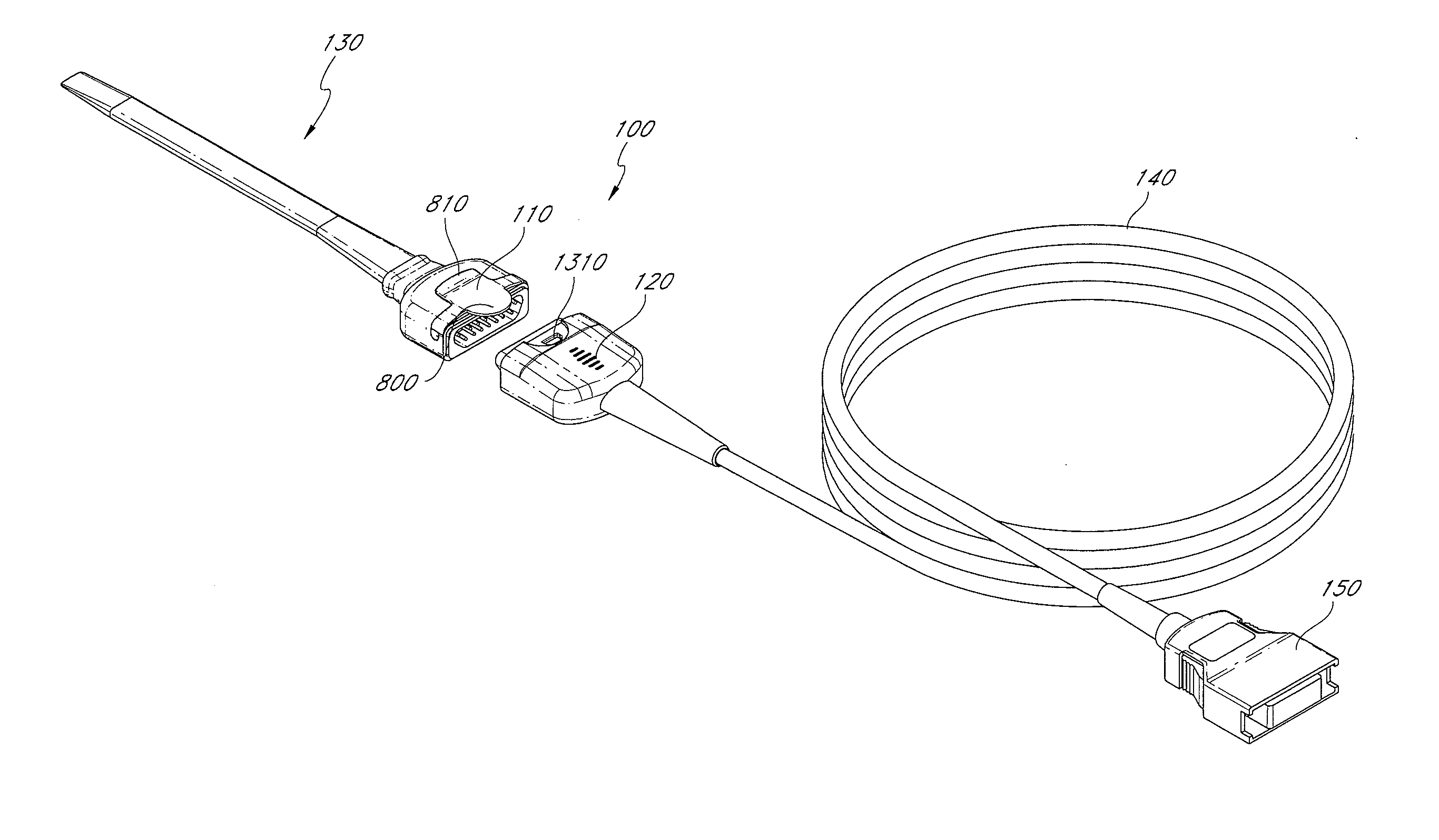
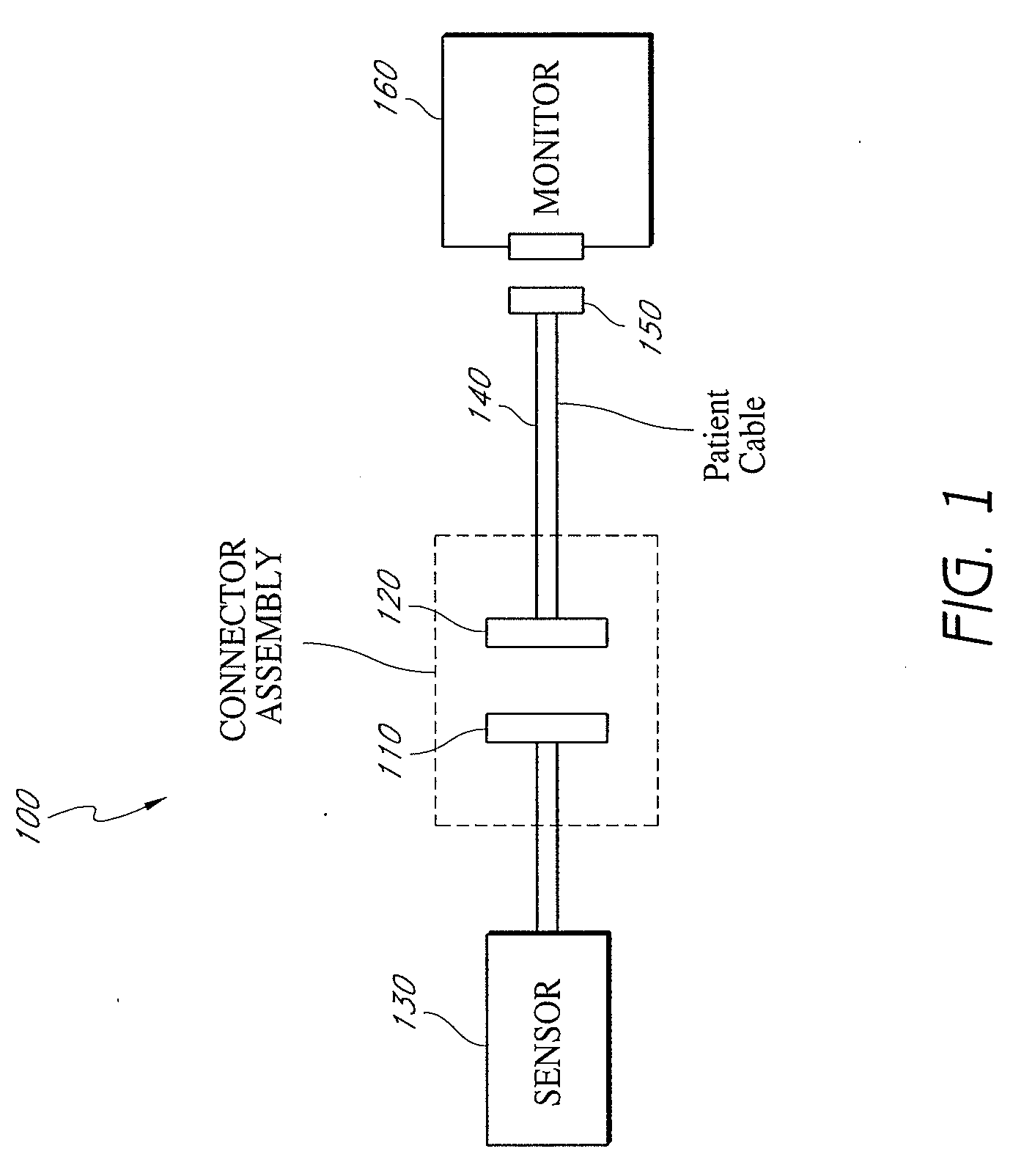
[0037]FIG. 1 generally illustrates a connector assembly 100 as part of a patient monitoring system. The connector assembly 100 allows a sensor 130 to communicate with a monitor 160 via a patient cable 140 including wires and / or conductors that interconnect the patient cable connector 120 and a monitor connector 150. The connector assembly 100 includes a sensor connector 110 and a patient cable connector 120 and, advantageously, allows for relatively straightforward and efficient connection and separation of a sensor 130 from a patient cable 140. For example, the sensor 130 and patient cable 140 can be separated relatively straightforwardly and efficiently by a user, such as, for example, by single-handed separation. In various embodiments, the patient cable connector accepts different types of sensors and sensor configurations. For example, in one embodiment, the patient cable connector 120 accepts a wide variety of standard SPO2 sensors. In another embodiment, the patient cable con...


PUM


Abstract

A connector assembly according to embodiments of the present disclosure is advantageously configured to allow a sensor connector to straightforwardly and efficiently join with and detach from a patient cable connector. Further, embodiments of the connector assembly advantageously reduce un-shielded area in an electrical connection between a patient cable and a sensor connector. In addition, embodiments of the connector assembly advantageously increase the shielding of detector signals coming from the patient sensor to the monitor.

Description

RELATED CASES[0001]The present application claims priority benefit under 35 U.S.C. § 119(e) from U.S. Provisional Application No. 60 / 979,674, filed Oct. 12, 2007, entitled, “Connector Assembly,” and U.S. Provisional Application No. 61 / 032,936, filed Feb. 29, 2008, entitled, “Connector Assembly,” which are incorporated by reference herein.[0002]The present disclosure is generally related to U.S. Provisional Application Ser. No. 60 / 846,260, filed Sep. 20, 2006, to U.S. patent application Ser. No. 11 / 858,818, filed Sep. 20, 2007, to U.S. Design Pat. application No. 29 / 296,064, filed Oct. 12, 2007, to U.S. Design Pat. application No. 29 / 296,067, filed Oct. 12, 2007 and to U.S. Design Pat. application No. 29 / 304,439, filed Feb. 29, 2008, which are incorporated herein by reference.FIELD OF THE DISCLOSURE[0003]The present disclosure is generally related to patient monitoring cable connector assemblies.BACKGROUND OF THE DISCLOSURE[0004]Pulse oximetry provides a noninvasive procedure for mea...

Claims


Application Information

Patent Timeline
IPC IPC(8): A61B5/00H01R13/648H01R13/62
CPCA61B5/1455A61B2562/227H01R13/6275H01R13/6683H01R2201/20H01R13/6581H01R2201/12H01R13/6585H01R13/6599
Inventor AL-ALI, AMMARFORREST, KEVINABDUL-HAFIZ, YASSIRYANG, ERIC
Owner JPMORGAN CHASE BANK NA
Why Eureka
Try Eureka