

Intervertebral implant
- Summary
- Abstract
- Description
- Claims
- Application Information
AI Technical Summary
Benefits of technology
Problems solved by technology
Method used
Image

Examples
Embodiment Construction
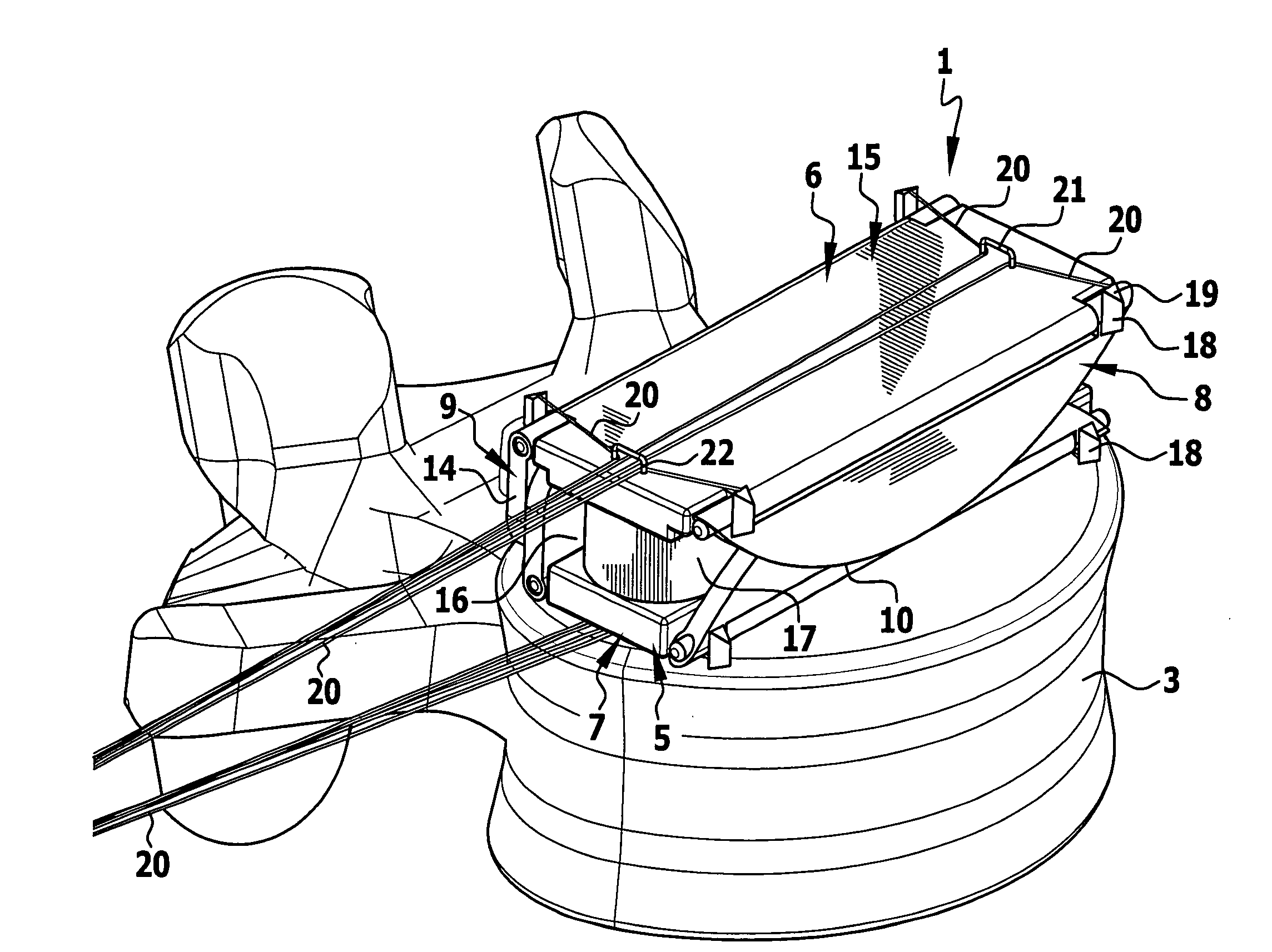
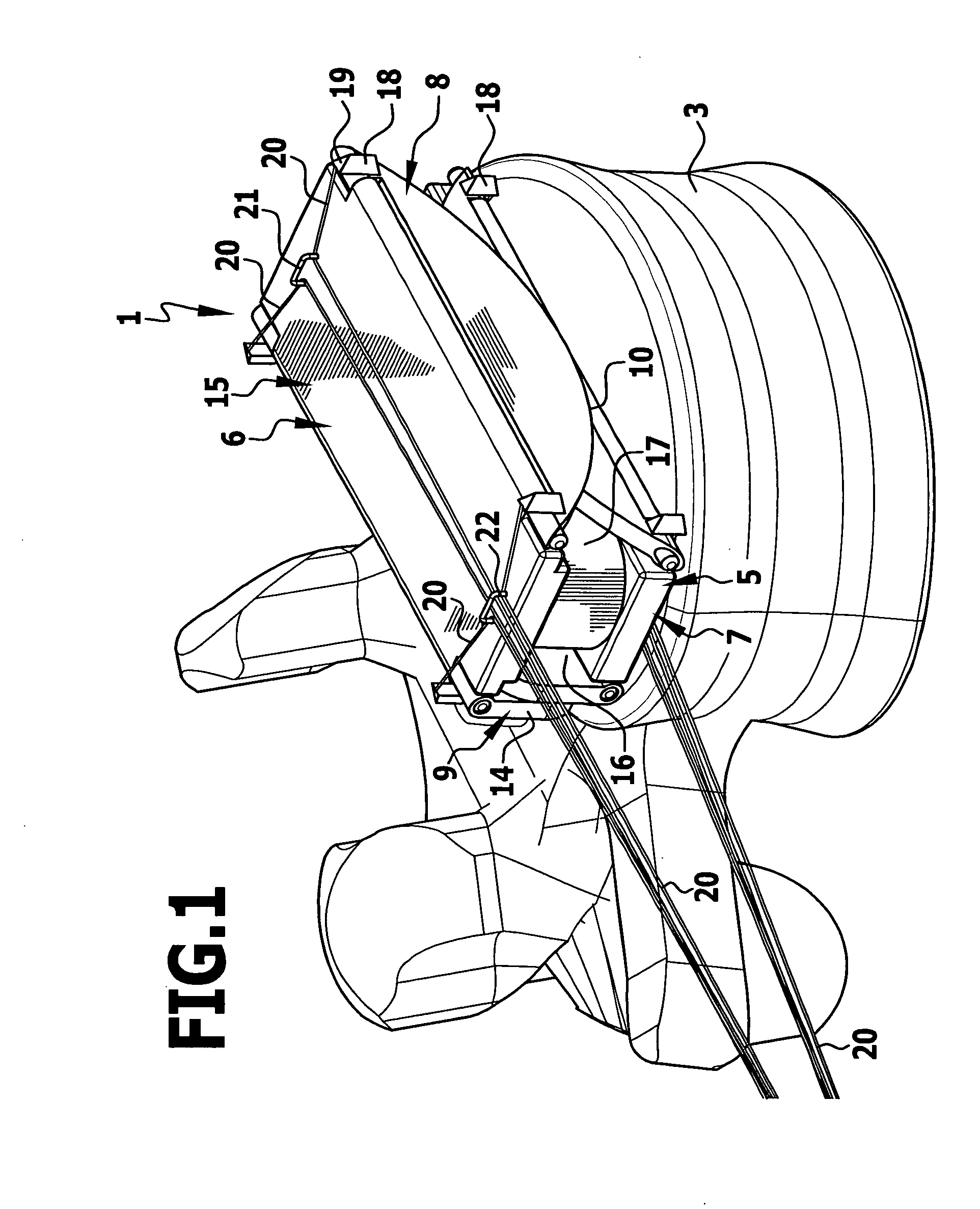
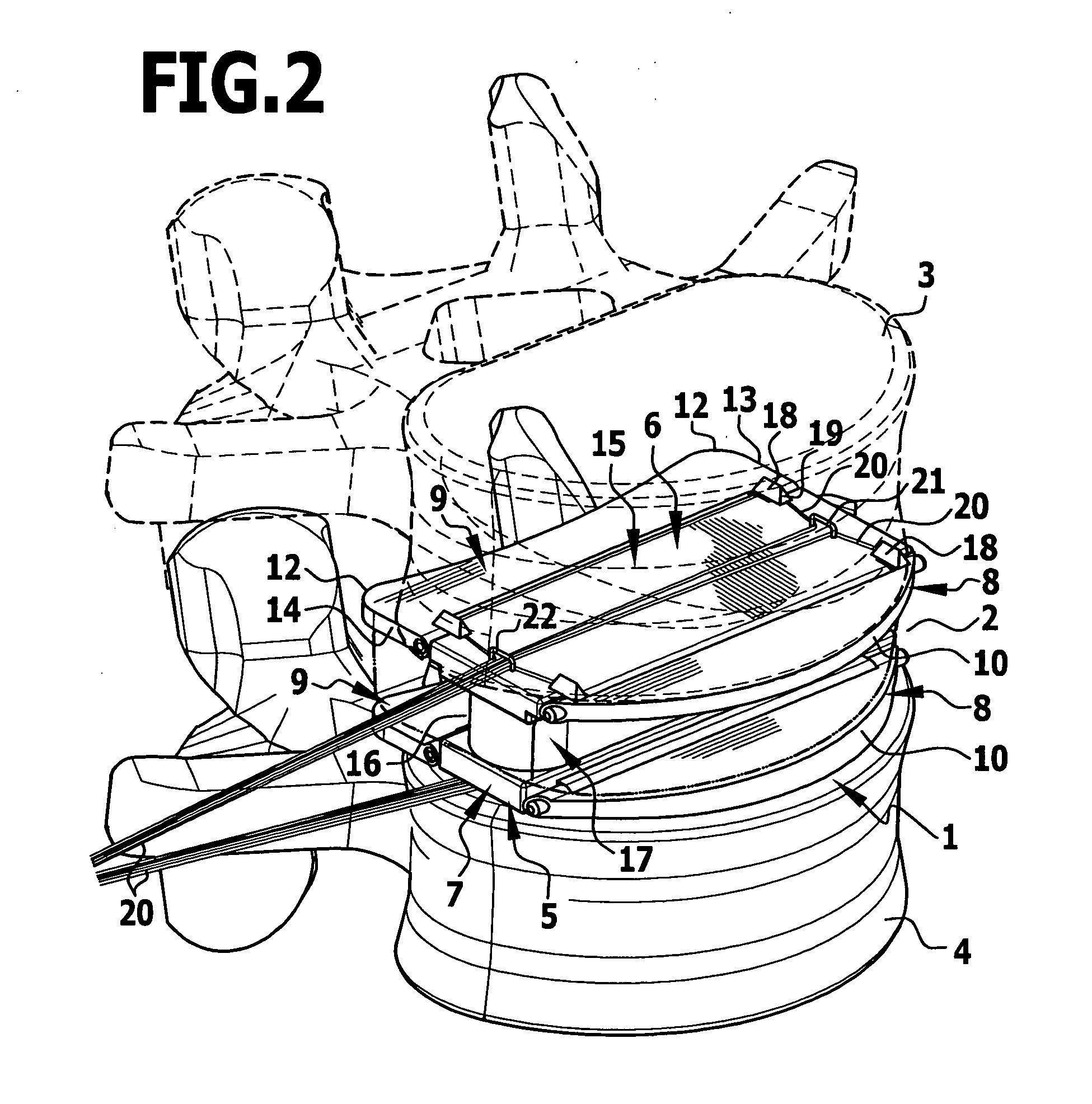
[0042]The intervertebral implant 1 shown in the drawing is inserted between two vertebral bodies 3, 4 during implantation into the intervertebral space 2 and there replaces the intervertebral disc removed from the intervertebral space 2. On its underside and on its upper side the intervertebral implant 1 shown in the drawing comprises a respective abutment element 5 and 6, which are both identical in configuration, but arranged mirror-inverted to one another. Only one of the two abutment elements will be explained in more detail below.
[0043]The abutment element 5 has a central, plate-like support section 7 with a rectangular cross-section, on the longitudinal sides of which a plate-like pivot part 8, 9 is respectively disposed to pivot around a pivot axis running along the longitudinal edges. One pivot part has the shape of a sector of a circle with an arc-shaped outer edge 10, the other pivot part 9 is substantially rectangular, but the outer edge 11 remote from the pivot axis is c...
PUM
| Property | Measurement | Unit |
|---|---|---|
| Fraction | aaaaa | aaaaa |
| Fraction | aaaaa | aaaaa |
| Length | aaaaa | aaaaa |
Abstract
Description
Claims
Application Information