Minimally invasive lateral intervertbral fixation system, device and method

a technology of lateral intervertebral fixation and lateral intervertebral bone, which is applied in the field of minimally invasive lateral intervertebral fixation system, device and method, can solve the problems of frequent deterioration, loss of normal consistency and volume of the spinal disk, and becoming a source of pain

Active Publication Date: 2009-04-16
INT SPINAL INNOVATIONS
View PDF20 Cites 167 Cited by
  • Summary
  • Abstract
  • Description
  • Claims
  • Application Information

AI Technical Summary

Benefits of technology

[0009]In a particular embodiment, an intervertebral fixation device is disclosed. The device includes a weight-bearing shell configured to fit into a disk space between plural vertebrae, the weight-bearing shell including plural sidewalls, a back wall and a front wall, a top surface and a bottom surface, the weight-bearing shell including a keyway opening between and through the plural sidewalls and plural openings between and through the top surface and the bottom surface that form a plurality of open chambers to an exterior of the shell. The intervertebral fixation device includes a first plurality of anchors adapted to penetrate and secure to a first vertebra, the first plurality of anchors rotatably coupled to the shell at a first axis of rotation proximate the top surface, the first plurality of anchors rotatably disposed in a first orientation in relation to the weight-bearing shell. The intervertebral fixation device

Problems solved by technology

Articulations between bony vertebrae of a human spine—such as spinal disks and facet joints—frequently deteriorate with age or trauma and become a source of pain.
Spinal disk deterioration causes the spinal disk to lose its normal consistency and volume, which facilitates the spinal disk to collapse and to cause abnormally painful motion across the spinal disk within the spine.
The abnormal motion across the deteriorating spinal disk also increases the stresses on the facet joints

Method used


Image

  • Minimally invasive lateral intervertbral fixation system, device and method
  • Minimally invasive lateral intervertbral fixation system, device and method
  • Minimally invasive lateral intervertbral fixation system, device and method

Examples


first embodiment

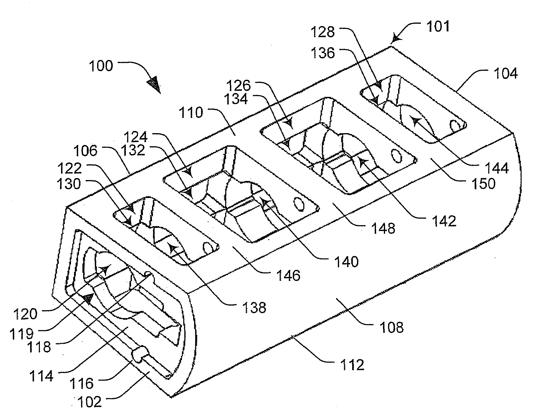
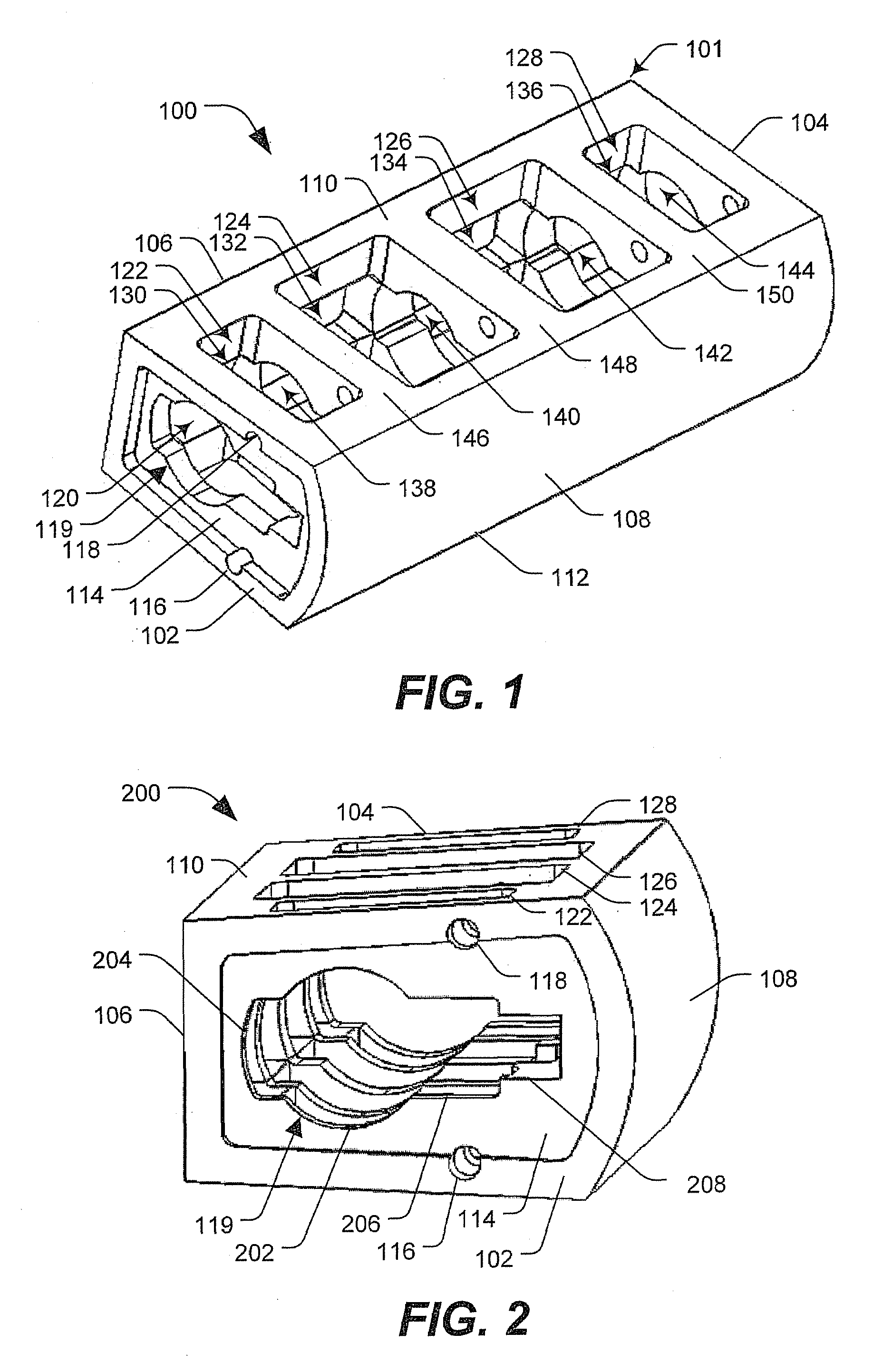
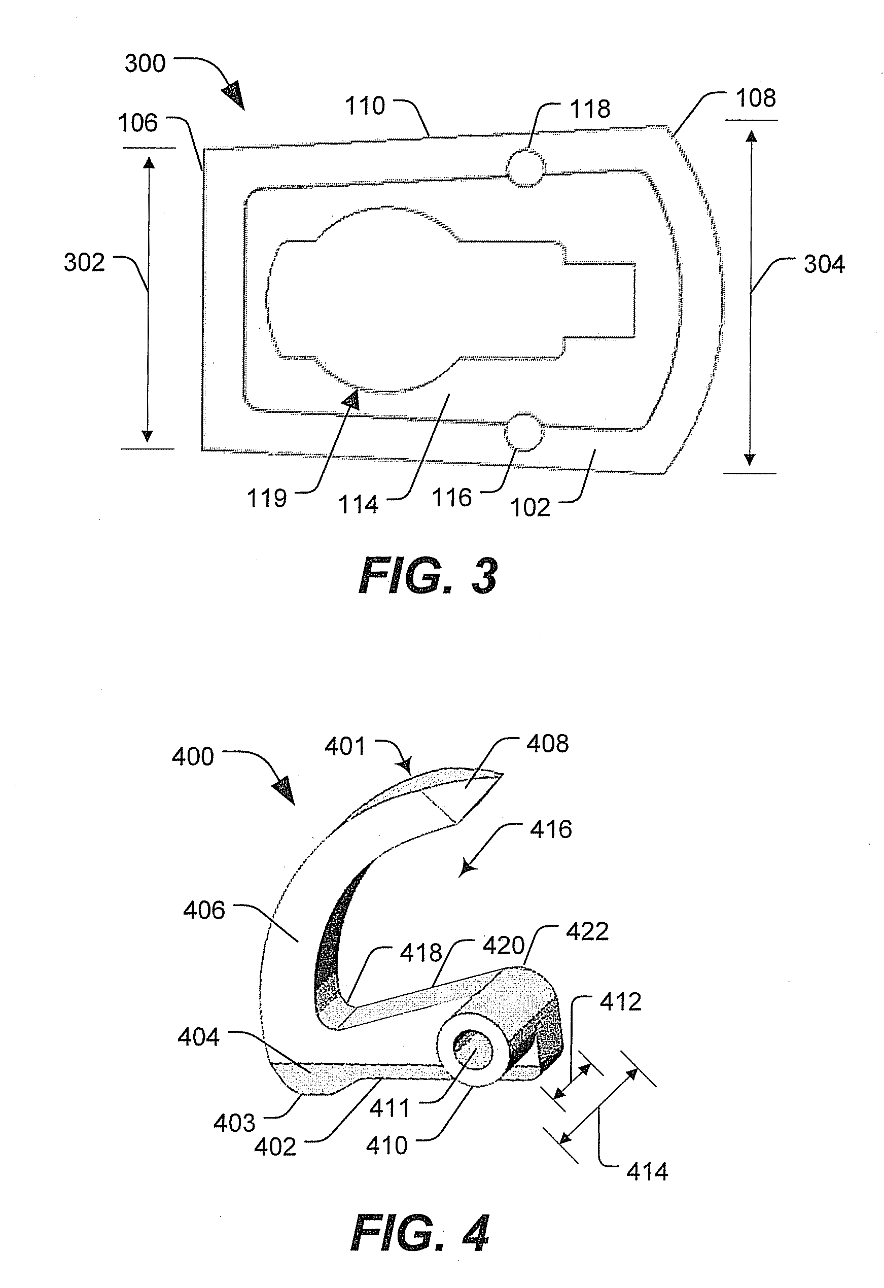
[0035]FIG. 7 is a perspective view 700 of a minimally invasive lateral intervertebral system 701. The minimally invasive lateral intervertebral system 701 includes an example wedge 702 and an example cylindrical key 704 to interface with the example shell 101 and the example plural anchors 602-616. The wedge 702 and cylindrical key 704 are used to rotate the respective sets of anchors (602, 610), (604, 612), (606, 614), and (608, 616), in order from the proximal to the distal, from a concealed position within the shell 101 into an extended and fixed position in relation to the shell 101 (shown in FIG. 11) to engage and secure endplates of respective vertebrae (not shown). For example, the wedge 702 is advanced forward (e.g., via portions 206 and 208 of the keyway 119) to rotate a first proximal set of anchors (602, 610) from the concealed position within the shell 101 to an intermediately rotated position in which the base portions of the set of anchors (e.g., base portion 402 of FI...

second embodiment

[0037]FIG. 9 is a perspective view of a minimally invasive lateral intervertebral system 900. The minimally invasive lateral intervertebral system 900 includes an example introducer 901, the shell 101 with plural anchors 602-616, the wedge 702, the cylindrical key 704 (shown in FIG. 10) and an extender / connector 907. The introducer 901 interfaces with the shell 101 and the cylindrical key 704 to deliver and implant the shell 101, the plural anchors 602-616 and the cylindrical key 704 (e.g., the minimally invasive lateral intervertebral fixation device) into a disk space between plural vertebrae.

[0038]The introducer 901 is made of a rigid radiolucent material, such as a radiolucent metal. In various embodiments, the radiolucent metal may be aluminum, beryllium or other radiolucent metal. In a particular embodiment, the introducer 901 is approximately 20 cm long and has a hollow configuration that approximates the shell 101 shown in FIG. 1. The introducer includes a mating protrusion ...


PUM


Abstract

A system, device and method are disclosed for minimally invasive lateral intervertebral fixation. An intervertebral fixation device includes a weight-bearing shell configured to fit into a disk space between plural vertebrae, the weight-bearing shell including a keyway opening between and through plural sidewalls. A first plurality of anchors is rotatably disposed in a first orientation in relation to the weight-bearing shell. A second plurality of anchors is rotatably disposed in a second orientation in relation to the weight-bearing shell. A key is adapted to rotate the first plurality of anchors in divergent directions from the second plurality of anchors and to secure a first vertebra and a second vertebra, respectively. The key is further adapted to support the first plurality of anchors and the second plurality of anchors in divergent directions in relation to the weight-bearing shell, the first plurality of anchors and the second plurality of anchors secured to the first vertebra and the second vertebra.

Description

CROSS-REFERENCE TO RELATED APPLICATIONS[0001]This application claims priority to and the benefit of U.S. Provisional Patent Application Ser. No. 60 / 998,376, which was filed Oct. 11, 2007 and entitled “Lateral Fixating Interbody Device,” and which is incorporated herein by reference in its entirety.FIELD [0002]The present disclosure relates generally to spinal fusion devices. More specifically, example embodiments are directed a minimally invasive lateral intervertebral system, device and method.DESCRIPTION OF RELATED ART[0003]Articulations between bony vertebrae of a human spine—such as spinal disks and facet joints—frequently deteriorate with age or trauma and become a source of pain. Spinal disk deterioration causes the spinal disk to lose its normal consistency and volume, which facilitates the spinal disk to collapse and to cause abnormally painful motion across the spinal disk within the spine. The abnormal motion across the deteriorating spinal disk also increases the stresses...

Claims


Application Information

Patent Timeline
IPC IPC(8): A61B17/70A61F2/44A61B17/04
CPCA61F2002/30784A61F2002/30515A61F2/4455A61F2220/0025A61F2/447A61F2002/30579A61F2002/30492A61F2002/30471A61F2/4611A61F2220/0091A61F2002/4627A61F2/30771A61F2002/30841
Inventor AFERZON, JOSEPHBASH, JEFFREY A.
Owner INT SPINAL INNOVATIONS
Why Eureka
Try Eureka