Method and apparatus for detecting defects in oilfield tubulars

a technology of oilfield tubulars and methods, applied in the field of methods and apparatus for detecting defects in oilfield tubulars, can solve problems such as types of problems

Inactive Publication Date: 2009-04-23
NEIDHARDT DEITMAR J
View PDF24 Cites 51 Cited by
  • Summary
  • Abstract
  • Description
  • Claims
  • Application Information

AI Technical Summary

Benefits of technology

[0006]A non destructive ultrasonic inspection unit senses defects in a tubular while remaining in situ, and without the need to bring the tubular to surface for inspection. Should cracks or wall thickness loss be identified, the sizing of the defect on location and in real time allows the offshore operator / drilling contractor to make a knowledgeable decision as to when and how to proceed with remediation of any defect encountered.

Problems solved by technology

Oilfield tubulars descend in a generally vertical direction within a well, and various types of connections are used to couple oilfield tubulars, thereby creating various types of problems when a sensor passes by an interface.

Method used


Image

  • Method and apparatus for detecting defects in oilfield tubulars
  • Method and apparatus for detecting defects in oilfield tubulars
  • Method and apparatus for detecting defects in oilfield tubulars

Examples


Embodiment Construction

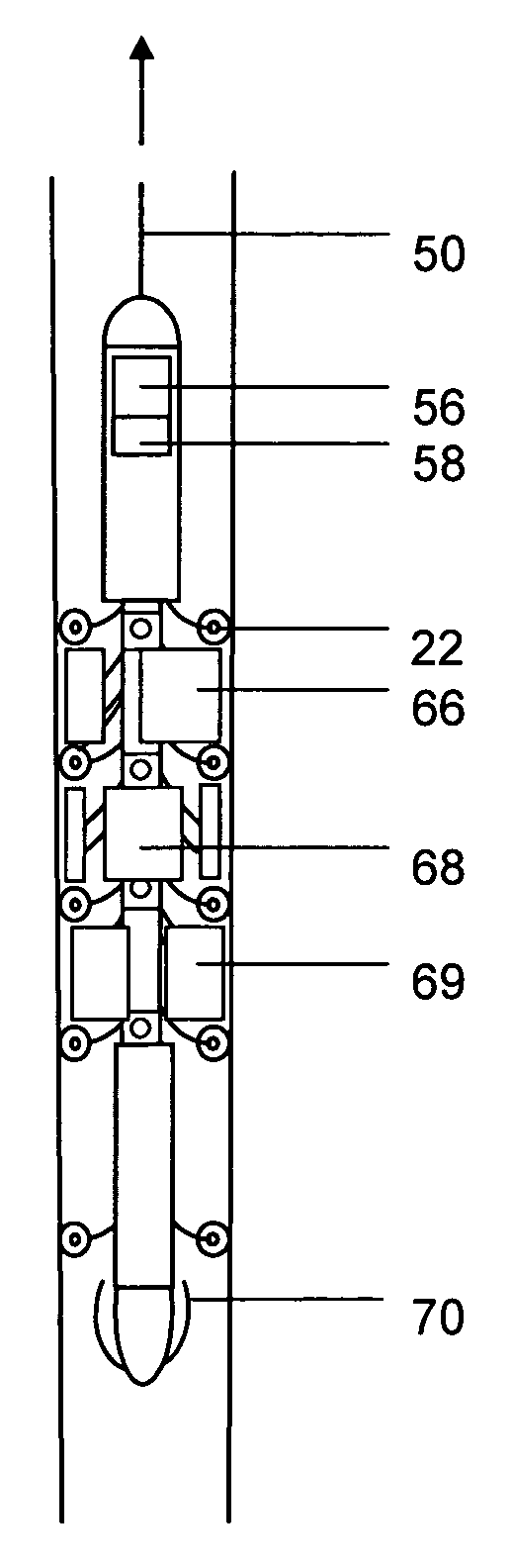
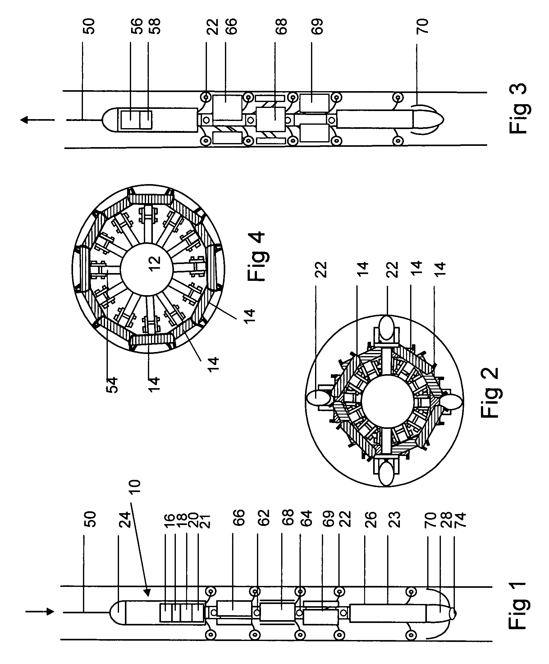
[0023]In one embodiment, the inspection tool 10 is connected to a flexible line or cable 50, which in turn is spooled on a drum, which may be located in a logging unit placed on the deck of a subsea drilling or production vessel or platform. The tool operation and movement may be controlled by the wire line logging unit and its operator during all the stages of activity. A multi-conductor cable 50 may serve as a conduit for commands sent to the tool and information data obtained by the tool during the process calibration and the measuring activities. Data transmitted by the tool may be directly forwarded into the surface computer system, typically located in the logging unit, allowing for real time data read out and analyses on site. Areas of particular interest along the tubular string may be repeatedly inspected without the need for pulling the tool to surface. The obtained results on the inspected tubular may assist in making intelligent decisions about the handling and the maint...


PUM


Abstract

A sensor system for detecting defects in a tubular string while positioned in the well includes a sensor tool (10) comprising a plurality of circumferentially spaced sensors (40) arranged in two or more axially spaced rows. A plurality of sensors are positioned in each row, with each sensor positioned on one of a plurality of sensor support pads. Sensors within a row may include sensors with axes inclined at different angles, and each of the plurality of sensor pads may move from a radially retracted run-in position to a radially extended sensing position. A flexible line (50) may be used for lowering a sensor tool in the well and retrieving the sensor tool from the well.

Description

FIELD OF THE INVENTION[0001]The present invention relates to techniques for detecting defects, such as corrosion or cracks, in an oilfield tubular while the tubular remains in situ in the well. More particularly, the invention relates to an improved technique for detecting defects in risers commonly used in subsea drilling and production operations.BACKGROUND OF THE INVENTION[0002]Various techniques have been used for detecting defects in metal flowlines. “Pigs” have been pumped through pipe liner for decades to of detect corrosion or cracks in the pipeline. The method and operation of a detection tool is considerably different, however, for oilfield applications, wherein the tubulars are conventionally inspected after they have been disassembled from the tubular string. Oilfield tubulars descend in a generally vertical direction within a well, and various types of connections are used to couple oilfield tubulars, thereby creating various types of problems when a sensor passes by an...

Claims


Application Information

Patent Timeline
Patent Type & Authority Applications(United States)
IPC IPC(8): E21B47/10
CPCF16L2101/30E21B47/08
Inventor NEIDHARDT, DEITMAR J.
Owner NEIDHARDT DEITMAR J
Why Eureka
Try Eureka