System and method to manufacture an implantable electrode

Active Publication Date: 2009-04-23
SAPIENS STEERING BRAIN STIMULATION
View PDF4 Cites 43 Cited by
  • Summary
  • Abstract
  • Description
  • Claims
  • Application Information

AI Technical Summary

Problems solved by technology

The majority of encapsulation methods for microfabricated electrodes are completed at the device level, rather tha

Method used


Image

  • System and method to manufacture an implantable electrode
  • System and method to manufacture an implantable electrode
  • System and method to manufacture an implantable electrode

Examples


Embodiment Construction

[0009]The following description of preferred embodiments of the invention is not intended to limit the invention to these embodiments, but rather to enable any person skilled in the art to make and use this invention.

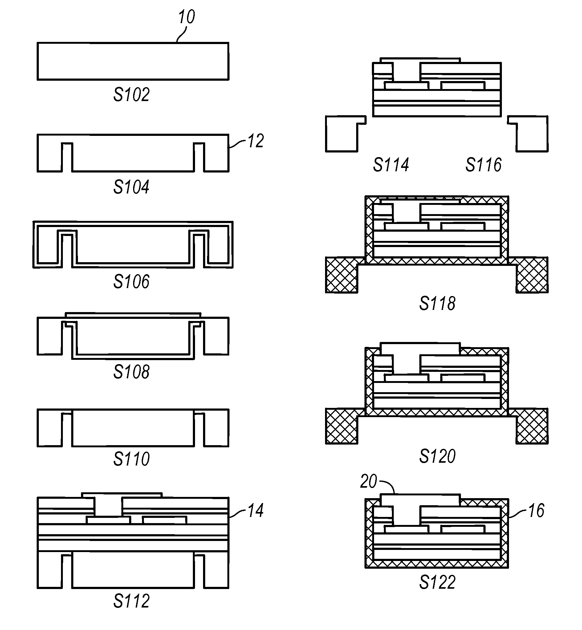
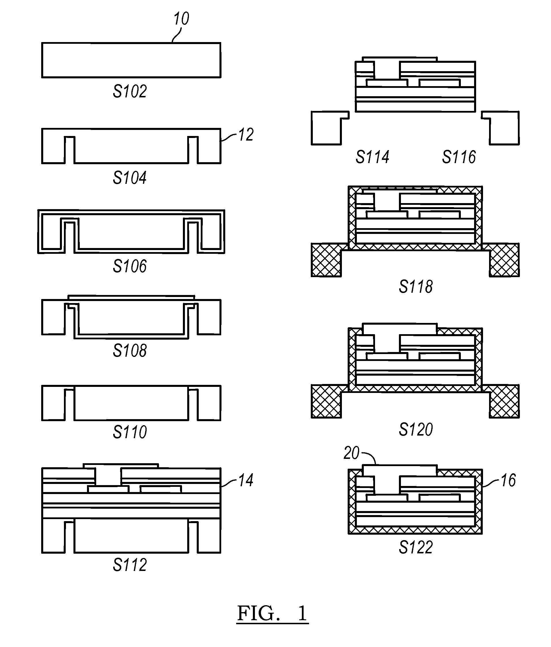
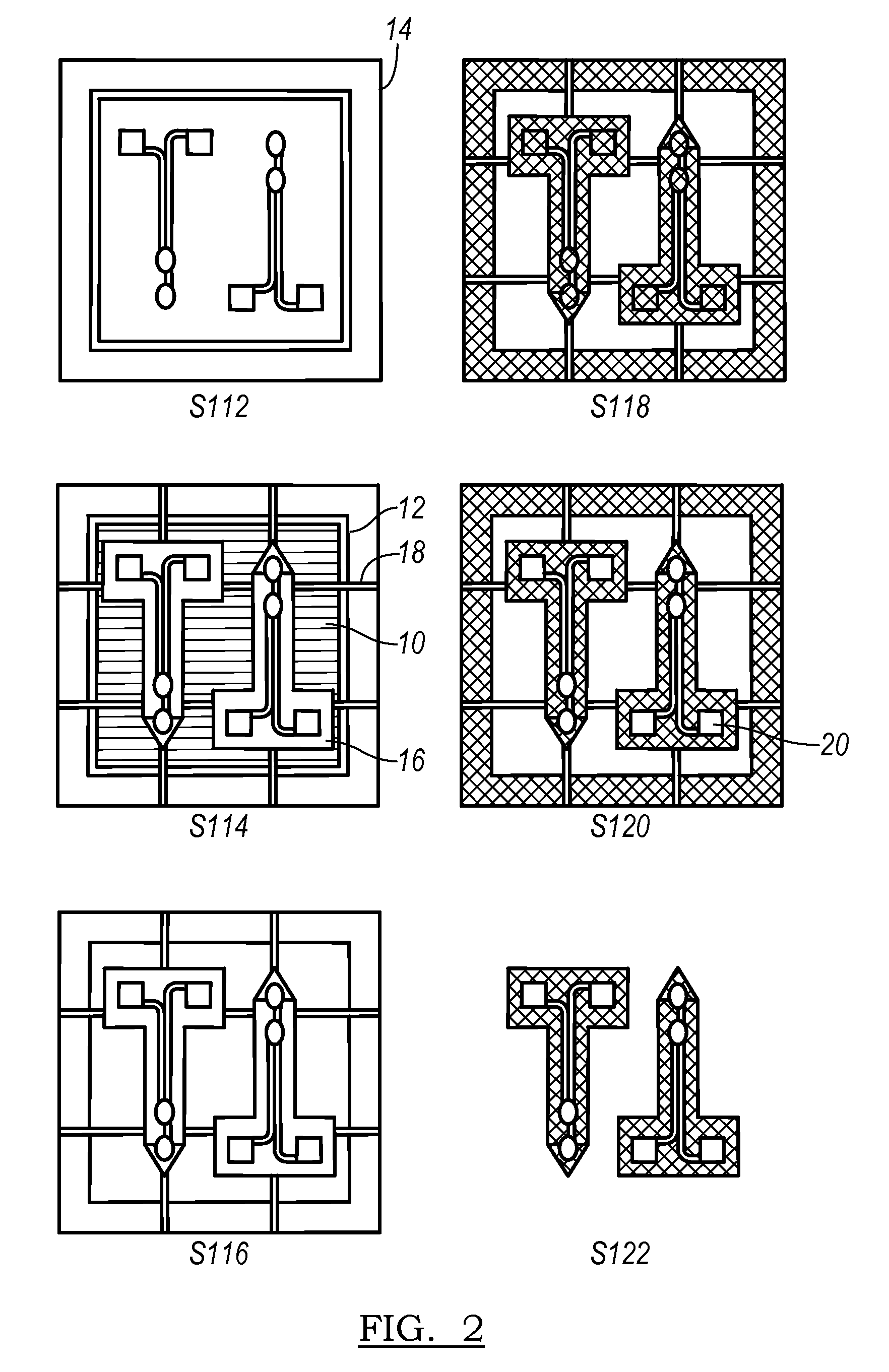
[0010]As shown in FIG. 6, the method of the preferred embodiments includes the steps of providing a base having a frame portion and a center portion S200; building a preliminary structure coupled to the base S112; removing a portion of the preliminary structure to define a series of devices and a plurality of bridges, wherein the series of devices are coupled to the center portion of the base, and wherein the plurality of bridges are coupled to the frame portion of the base and to the series of devices S114; removing the center portion of the base such that the frame portion defines an open region, wherein the plurality of bridges suspend the series of devices in the open region defined by the frame S202; and encapsulating the series of devices S204. The method is prefe...


PUM


Abstract

The method of the preferred embodiments includes the steps of providing a base having a frame portion and a center portion; building a preliminary structure coupled to the base; removing a portion of the preliminary structure to define a series of devices and a plurality of bridges; removing the center portion of the base such that the frame portion defines an open region, wherein the plurality of bridges suspend the series of devices in the open region defined by the frame; and encapsulating the series of devices. The method is preferably designed for the manufacture of semiconductor devices, and more specifically for the manufacture of encapsulated implantable electrodes. The method, however, may be alternatively used in any suitable environment and for any suitable reason.

Description

CROSS-REFERENCE TO RELATED APPLICATIONS[0001]This application claims the benefit of U.S. Provisional Application No. 60 / 980,662, filed 17 Oct. 2007 and entitled “Method to Manufacture an Implantable Electrode”, which is incorporated in its entirety by this reference.TECHNICAL FIELD[0002]This invention relates generally to the implantable electrodes field, and more specifically to an improved method to manufacture encapsulated implantable electrodes.BACKGROUND[0003]Conventional implantable electrodes are coated with dielectrics to provide increased protection from moisture absorption. The majority of encapsulation methods for microfabricated electrodes are completed at the device level, rather than the wafer level, and therefore are more labor intensive and preclude further batch processing of the electrodes. For example, when the devices are encapsulated at the device level, electrode sites must be exposed individually on each device, typically with laser ablation. Alternatively, wh...

Claims


Application Information

Patent Timeline
IPC IPC(8): H01L23/28H01L21/00
CPCH01L21/561H01L23/293H01L23/3185H01L2924/3025A61N1/05H01L2924/0002H01L23/49541H01L2924/00H01L2224/04105H01L2224/96
Inventor PELLINEN, DAVID S.HETKE, JAMILLE FARRAYEKIPKE, DARYL R.KONG, K. C.VETTER, RIO J.GULARI, MAYURACHAT
Owner SAPIENS STEERING BRAIN STIMULATION
Why Eureka
Try Eureka