Target Acquisition System

a target acquisition and target technology, applied in the field of target acquisition systems, can solve the problems of difficulty in ensuring the correct image is being displayed by one operating the controller, and achieve the effect of easy recall

Inactive Publication Date: 2009-04-23
GLOBAL DEVICE MANAGEMENT
View PDF13 Cites 48 Cited by
  • Summary
  • Abstract
  • Description
  • Claims
  • Application Information

AI Technical Summary

Benefits of technology

[0014]The method can further include storing the graphical overlay in a memory preset of the controller. In this regard, the controller can have a

Problems solved by technology

However, while the controller can display the original image, the zoomed and/or panned image is only visible on the display i

Method used


Image

  • Target Acquisition System
  • Target Acquisition System
  • Target Acquisition System

Examples


Embodiment Construction

[0021]While this invention is susceptible of embodiments in many different forms, there is shown in the drawings and will herein be described in detail preferred embodiments of the invention with the understanding that the present disclosure is to be considered as an exemplification of the principles of the invention and is not intended to limit the broad aspect of the invention to the embodiments illustrated.

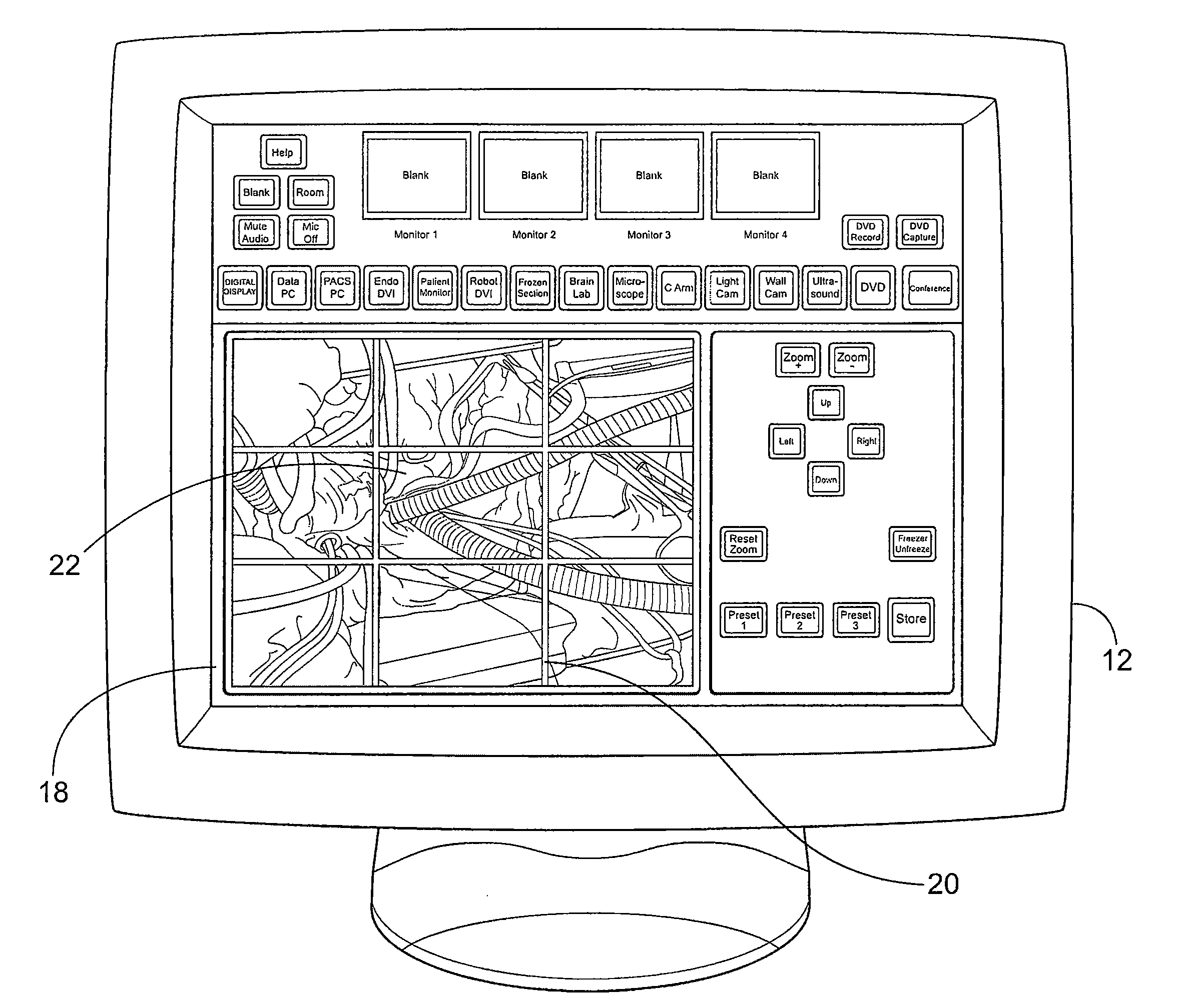
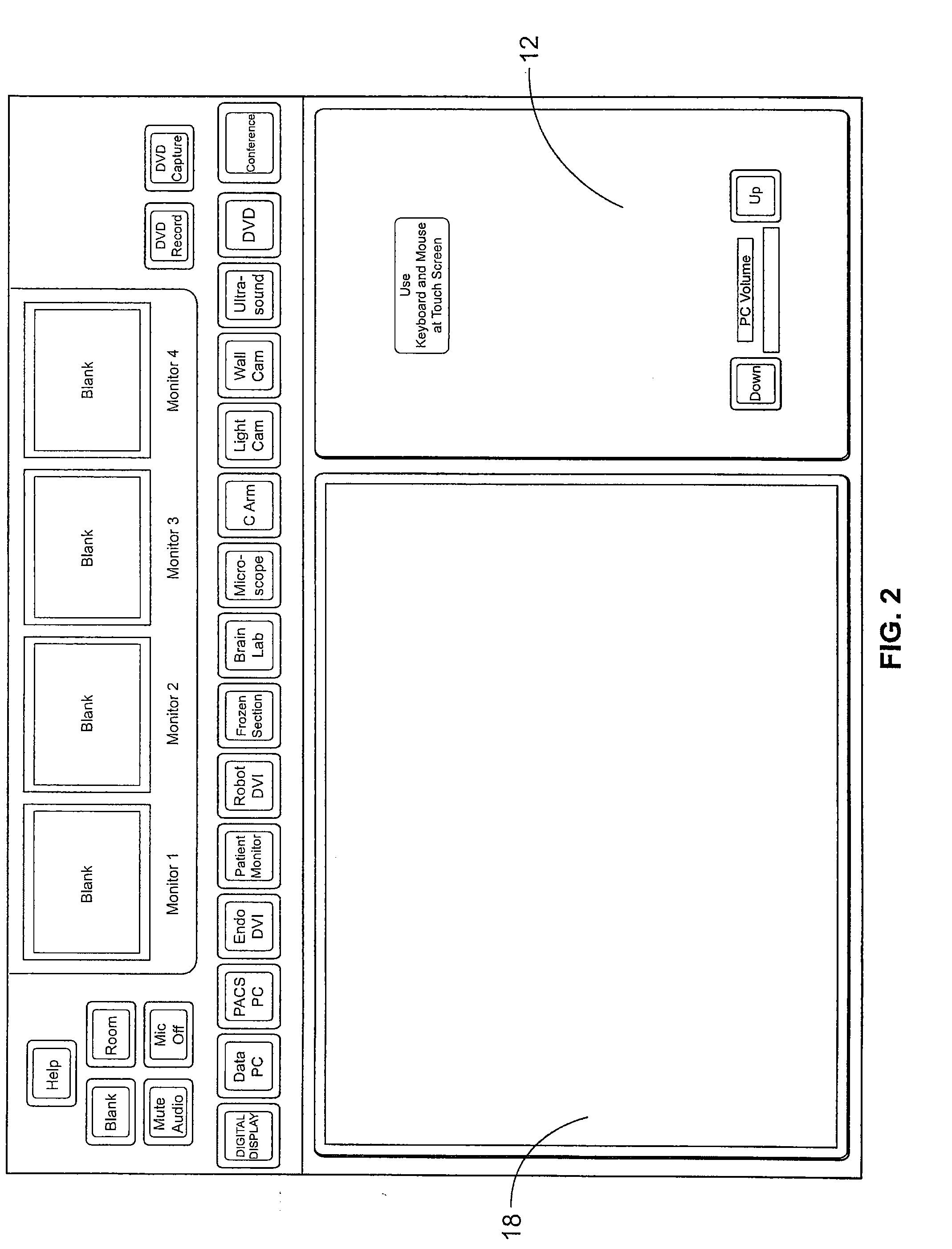
[0022]The present invention is utilized in connection with a video routing system. Such systems can be used in a hospital operating room for managing routing of video and data signals (i.e., data sources) and controlling hardware peripherals such as switches, computers, recorders and display monitors. The system is coordinated from a controller which includes a touch panel or computer display.

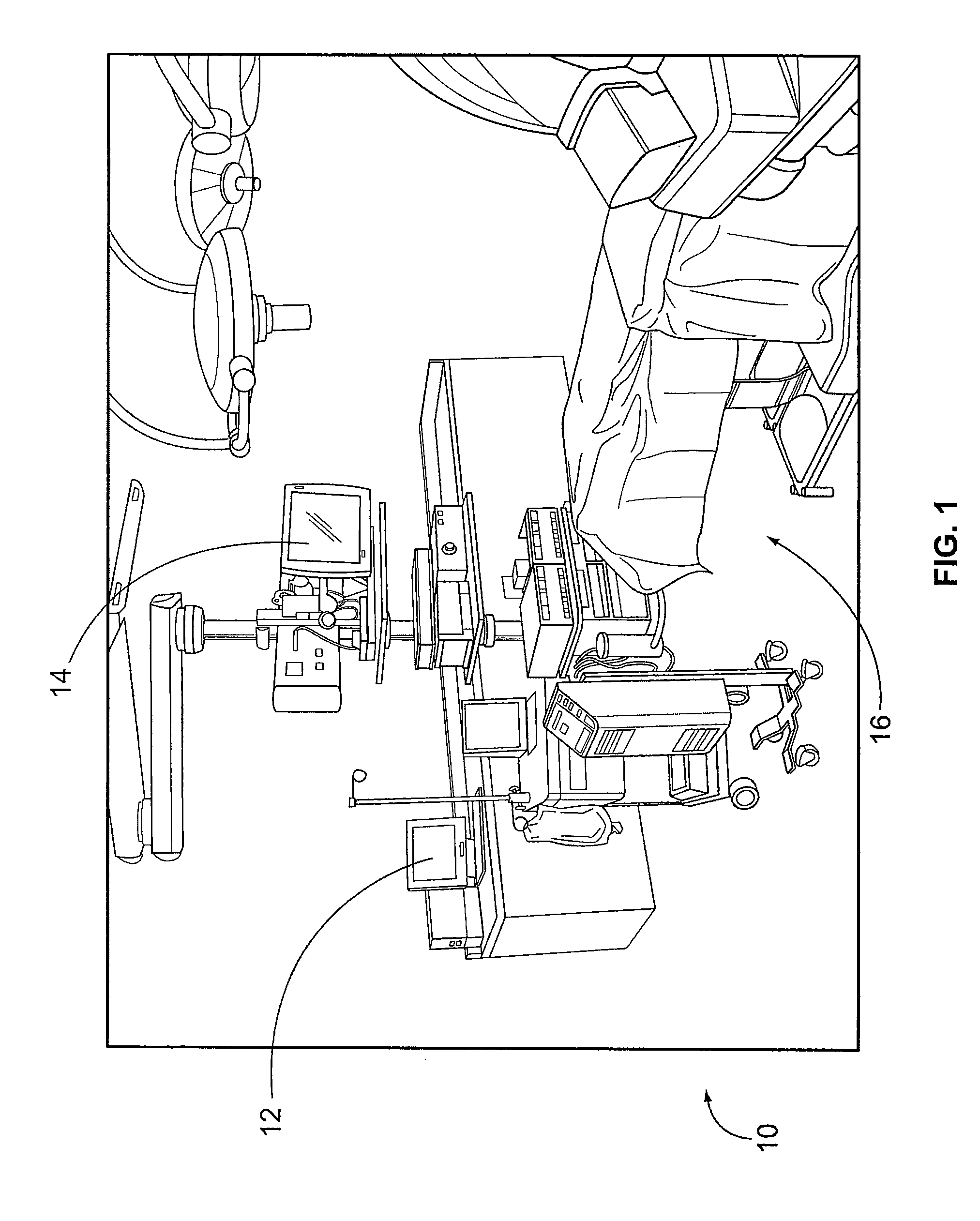
[0023]FIG. 1 shows a typical operating room 10 having a controller in the form of a controller touch panel 12 positioned off to one side, and a display device having a monitor or terminal ...


PUM


Abstract

A targeting system and method for remotely controlling the zoom and pan features of a device for display in an operating room is provided.

Description

CROSS-REFERENCE TO RELATED APPLICATIONS[0001]The present invention claims the benefit of U.S. Provisional Patent Application No. 60 / 995,094, filed Sep. 24, 2007, the contents of which are incorporated herein by reference.FEDERALLY SPONSORED RESEARCH OR DEVELOPMENT[0002]Not Applicable.TECHNICAL FIELD[0003]The invention generally relates to a system and method for allowing a controller in an operating room to control the zoom and pan features of one or more remote display terminals in the sterile area of the operating room; and more particularly, to a system and method for providing a graphical overlay at a control terminal for use in identifying and modifying an image appearing at a display terminal in the sterile area.BACKGROUND OF THE INVENTION[0004]In an operating room, various display terminals or devices are provided in the sterile area (i.e., the area proximate the patient) that show images utilized by the doctors and other clinicians assisting in the procedure at hand. A contr...

Claims


Application Information

Patent Timeline
IPC IPC(8): H04N5/232H04N5/262G06F3/041G06F3/048G16Z99/00H04N7/18
CPCG06F3/0481G06F3/04845H04N5/2628G06F2203/04806G06F19/3406G16H40/63G16Z99/00
Inventor HARRIS, DAVID P.CORMACK, RANDALL WAYNEBLOOM, JONATHAN G.
Owner GLOBAL DEVICE MANAGEMENT
Why Eureka
Try Eureka