Liquid flowing device

a technology of liquid flowing and spherical fluid, which is applied in the direction of positive displacement liquid engines, piston pumps, machines/engines, etc., can solve the problems of propeller mechanism limitation, seal obstruction, and pump size reduction

Inactive Publication Date: 2009-04-23
SEIKO EPSON CORP
View PDF4 Cites 3 Cited by
  • Summary
  • Abstract
  • Description
  • Claims
  • Application Information

AI Technical Summary

Benefits of technology

[0007]In accordance with an advantage of some aspects of the invention, it is possible to provide a liquid flowing device with a novel mechanism for flowing liquid.

Problems solved by technology

Such sealing may also pose an obstruction to size-reduction of pumps.
Similarly, pumps using a screw propeller mechanism need sealing devices for sealing liquid, and thus have a limitation in size-reduction.
Also, for example, the screw propeller mechanism has a drawback in that its efficiency considerably deteriorates when its rotation speed is increased in order to increase the fluid flow rate.

Method used


Image

  • Liquid flowing device
  • Liquid flowing device
  • Liquid flowing device

Examples


Embodiment Construction

[0038]A preferred embodiment of the invention is described below with reference to the accompanying drawings. It is noted that the embodiment described below explains an example of the invention.

[0039]1. Liquid Flowing Device

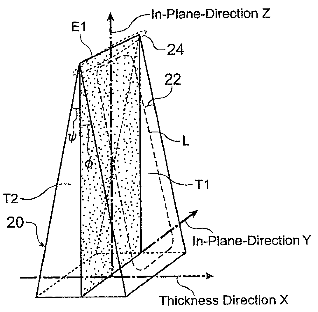
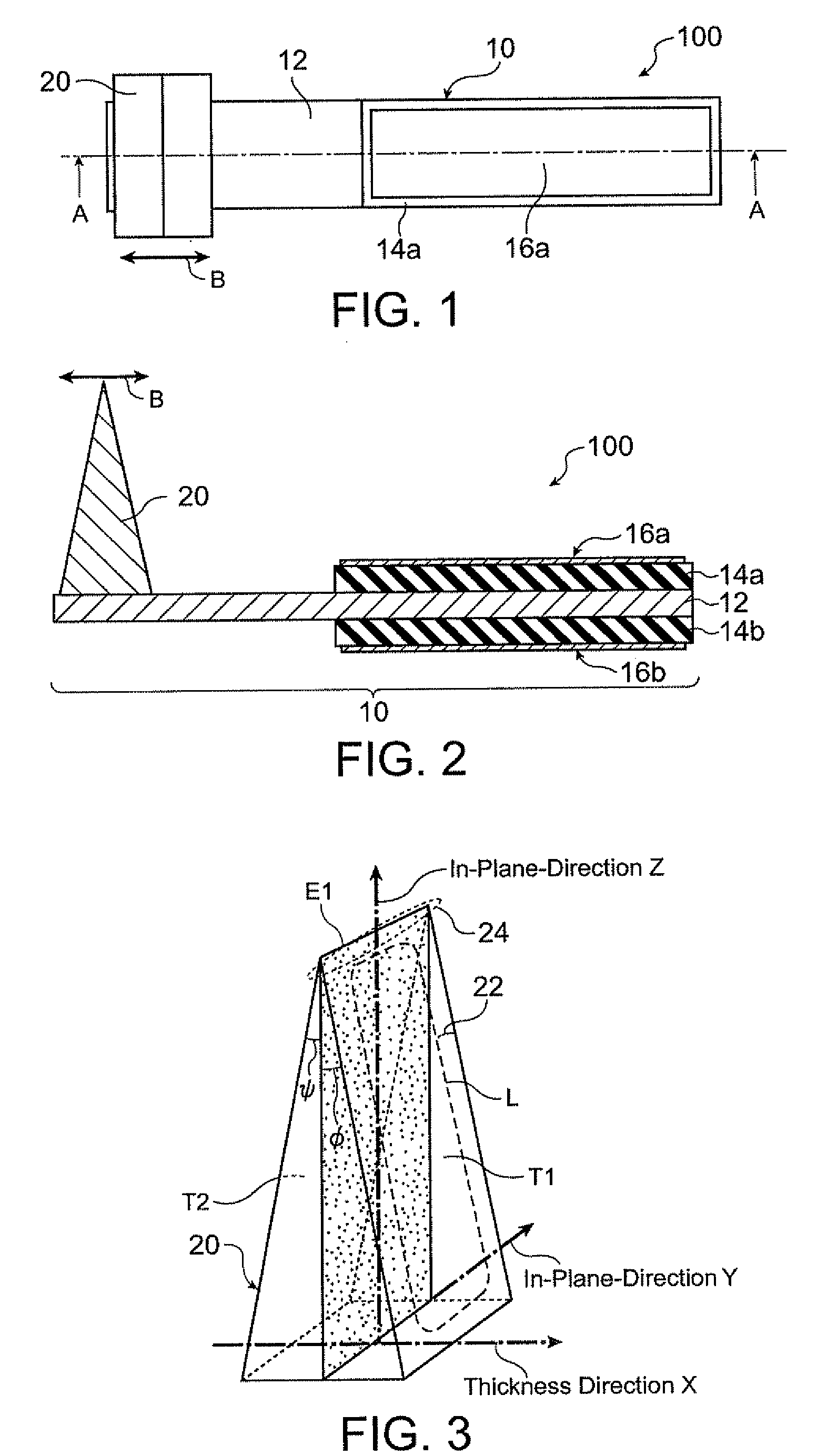
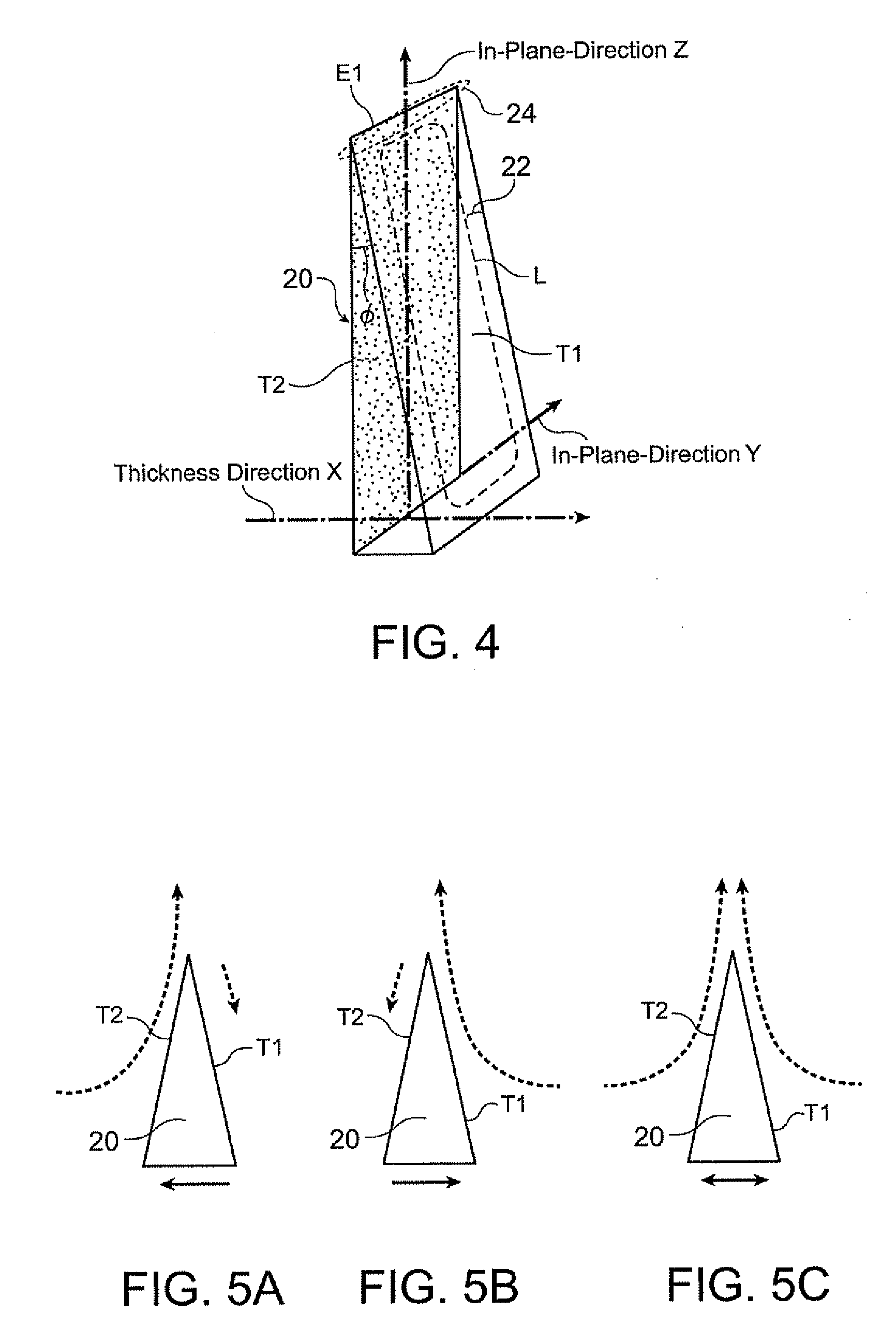
[0040]An example of a liquid flowing device 100 in accordance with an embodiment of the invention is described with reference to the accompanying drawings. FIG. 1 is a schematic plan view of the liquid flowing device 100 in accordance with the present embodiment. FIG. 2 is a schematic cross-sectional view of the liquid flowing device 100 in accordance with the embodiment of the invention. A cross section taken along a line A-A of FIG. 1 corresponds to FIG. 2. FIG. 3 and FIG. 4 are schematic perspective views of examples of driving sections 20 in accordance with the embodiment, respectively.

[0041]The liquid flowing device 100 has a driving section 10 and a vibration body 20.

[0042]The driving section 10 includes piezoelectric layers 14a and 14b with a base member ...


PUM


Abstract

A liquid flowing device includes: a plate-like vibration body; and a driving section that vibrates the vibration body in a thickness direction, wherein at least a portion of an end section of the vibration body in an in-plane direction continuously becomes thinner toward an end of the vibration body.

Description

BACKGROUND[0001]1. Technical Field[0002]The present invention relates to liquid flowing devices for flowing liquid.[0003]2. Related Art[0004]As devices for flowing liquid, screw propellers for ships and various types of pumps are available. Also, fish fins may be considered as devices for flowing liquid. Such device mechanisms use particular shapes and movements specifically selected to effectively flow liquid. In recent years, it has become necessary to achieve a further improvement in the efficiency of liquid flowing devices and a further size reduction thereof depending on their usage.[0005]The structure and principle of fish fins may be applied to pumps. For example, Japanese Laid-open Patent Application JP-A-5-272497 describes a pump for flowing liquid by reciprocally rotationally driving a fin about a rotary shaft within a specified angle range. The document describes that the pump can be formed with smaller and fewer components.[0006]However, in the case of a pump driven by a...

Claims


Application Information

Patent Timeline
Patent Type & Authority Applications(United States)
IPC IPC(8): F04B17/03
CPCF04F7/00F04B17/003
Inventor MIYAZAWA, OSAMU
Owner SEIKO EPSON CORP
Why Eureka
Try Eureka