
Media Case Date Indicator

a technology of media storage case and indicator, applied in the field of time indicators, can solve the problems of financial penalties, consumers' difficulty in remembering the due date of media rental, and often significant drawbacks of approaches

Inactive Publication Date: 2009-04-30
HELMSTETTER GREG
View PDF16 Cites 3 Cited by
  • Summary
  • Abstract
  • Description
  • Claims
  • Application Information

AI Technical Summary

Benefits of technology

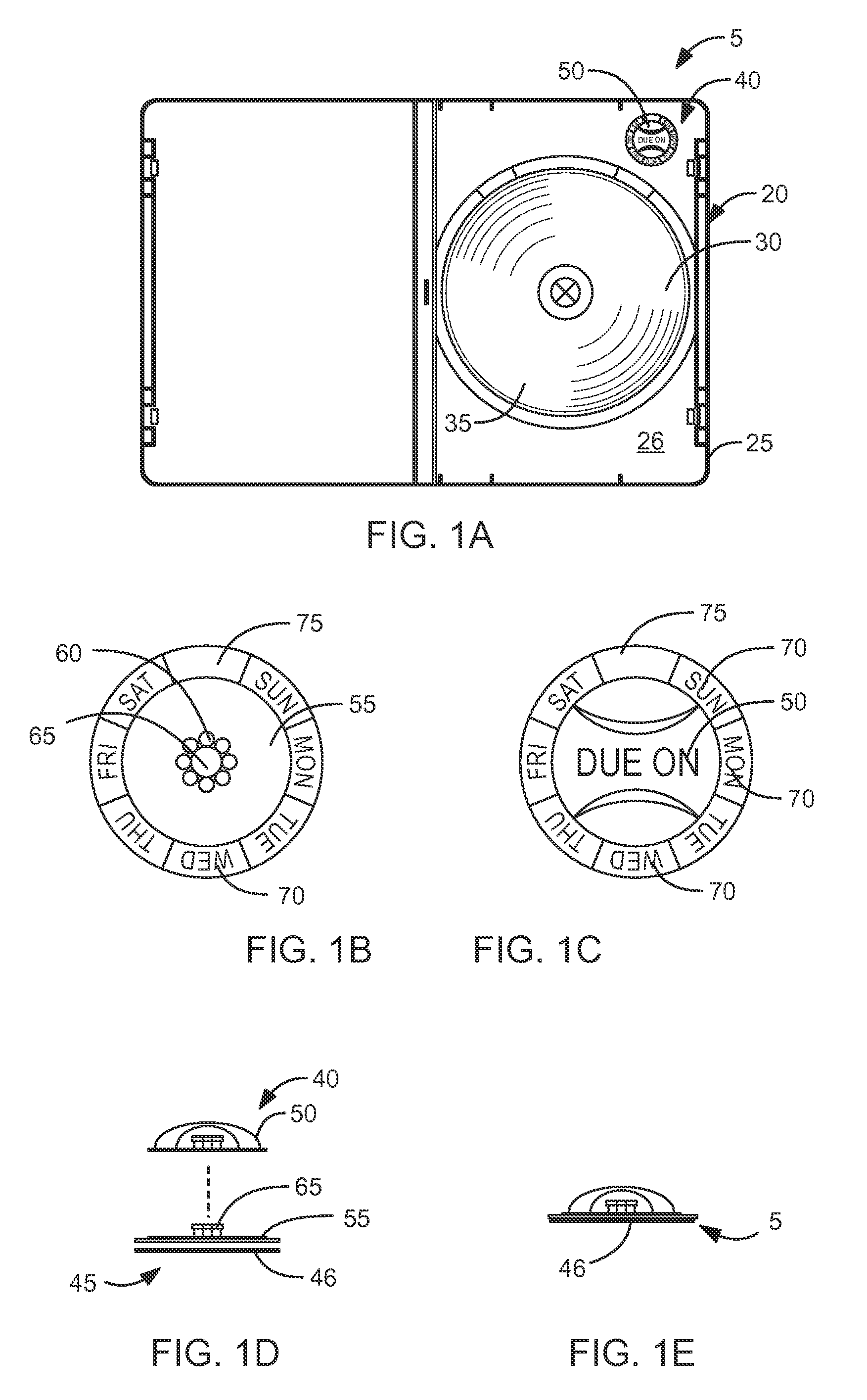
[0012]The present device is a media storage case mechanically adjustable time indicator for indicating the due-date of media items. One embodiment of the invention is an adjustable time indicator system for fixing to the media case. An alternate embodiment of the invention is an adjustable time indicator formed into the media case. The preferred embodiment of the invention indicates the day or date the media item is due, however, the invention can also easily indicate an hour or minute time the media item is due.
[0023]In one embodiment of the detent means, the detent means includes radial bumps on the outer circumference of the axle that are indexed to bumps on the interior of the rotary dial. In an alternate embodiment, the detent means includes notches on the media case radially extending away from the axle that are indexed to bumps on the bottom side of the rotary dial. Both embodiments provide an indexing action to click the rotary dial into place on the desired day (or date) and preventing free rotation without actuation of the rotary dial.
[0025]The present device is a time indicator device that will help remind consumers to return rental media on time by mechanically indicating the due date. The present invention is not easily misplaced or lost and can be permanently associated with the media case. The present device is easily used with existing rental systems and does not require consumers to purchase a separate reminder system. Also, the present device is economical and minimizes the cost to a business, yet still effectively provides a valued service to the consumer. Furthermore, the present invention provides a simple mechanical solution and is easily integrated with media cases. Other features and advantages of the present invention will become apparent from the following more detailed description, taken in conjunction with the accompanying drawings, which illustrate, by way of example, the principles of the invention.

Problems solved by technology

Despite the development of multiple approaches to remind consumers of rental due dates, these approaches often have significant drawbacks.
Without a reminder, consumers find it difficult to remember the due date of the media rental.
Forgetting to return a rental item on time can lead to financial penalties.
However, this approach leads to a problem if the receipt is misplaced or lost.
However, the Scott device requires the consumer to purchase a separate reminder system.
On the other hand, businesses would not be willing to pay for a reminder system, unless it financially benefited the business.
However, the Diggin's solution involves an electronic device which would be more expensive than a simple mechanical solution, especially if the devices are used on large numbers of media cases as would be the case in a media rental business.
Furthermore, the size of the electronic device is not insubstantial and would either make the exterior of media cases bulkier or would be difficult to integrate in a thin media case, such as a DVD case.
This sophisticated and electronic Capurso device does not teach a solution for a more economical and simple mechanical approach.

Method used


Image

  • Media Case Date Indicator
  • Media Case Date Indicator
  • Media Case Date Indicator

Examples


integrated embodiments

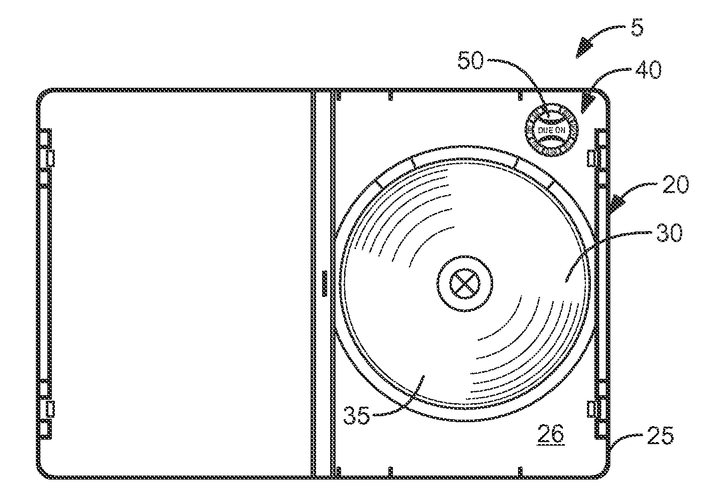
[0059]With respect to the drawings, FIGS. 3A, 4A, &5A illustrate a media storage system 10 including a media case 20 for selectively holding a media element 30 and a mechanically adjustable time indicator 40 formed into the media case 20. The media storage system 10 is preferably made of a light weight but durable plastic material, but can be made of any suitable light weight and durable material, if desired.

[0060]In a preferred embodiment illustrated in FIGS. 1A & 4A, the media element 30 is a media disk 35, and the media case 20 is a media disk 35 enclosing shell 25 having an internal side 26 and an external side 27. In the embodiment illustrated in FIG. 5A, the time indicator 40 is formed into the internal side 26 of the shell 25. In an alternate embodiment, the time indicator 40 is formed into the external side 27 of the shell 25. In a preferred embodiment, the external side 27 includes a thin edge portion 28 with the time indicator 40 being formed therein, as illustrated in FIG...

embodiment

Slidable Indicator Embodiment

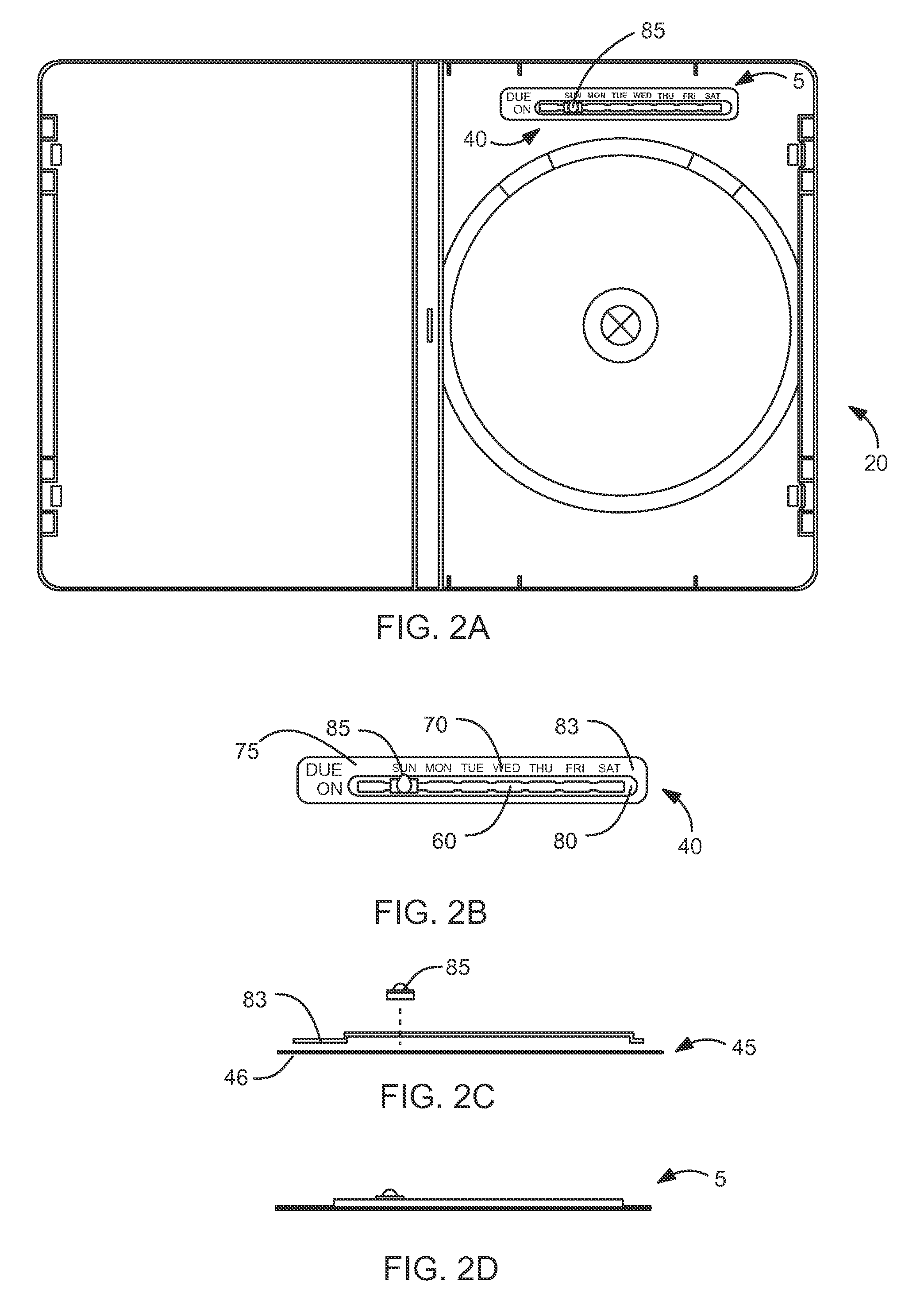
[0062]In an alternate embodiment of the media storage system 10 illustrated in FIGS. 4A, 4B, &4C, the time indicator 40 is a peg 85 slidably captured within a linear channel 80 formed into the media case 20. The linear channel 80 includes detent means 60 (FIG. 4B) such that the peg 85 may be selectively placed at one of a plurality of demarked indicator positions 70 therealong. The peg 85 indicates the due day (or date) by sliding to a desired indicator position 70.

[0063]In one embodiment, the linear channel 80 is formed by creating an aperture in the media case 20 to form the linear channel 80. In another embodiment, the linear channel 80 is created by forming a rectangular raised portion on the surface of the media case 20 and forming a linear channel 80 in that raised portion. In a preferred embodiment, the linear channel 80 is form in the thin edge portion 28, as illustrated in FIG. 4C. This embodiment is preferred because the time indicator 40 can b...


PUM


Abstract

The present device relates to a media storage case mechanically adjustable time indicator for indicating the due date of media elements. One embodiment of the invention is an adjustable time indicator system for fixing to the media case. An alternate embodiment of the invention is an adjustable time indicator formed into the media case itself. The invention includes multiple embodiments of the time indicator including but not limited to a rotary dial embodiment, a slidable indicator embodiment, a peg hole indicator embodiment, and a deformable button embodiment.

Description

CROSS-REFERENCE TO RELATED APPLICATIONS[0001]Not Applicable.STATEMENT REGARDING FEDERALLY SPONSORED RESEARCH AND DEVELOPMENT[0002]Not Applicable.FIELD OF THE INVENTION[0003]This invention relates to time indicators, and more particularly to a media storage case time indicator.DISCUSSION OF RELATED ART[0004]Time indicators associated with rental media cases are well known in the art. For example, U.S. Pat. No. 6,933,834 to Diggins, Jr. on Aug. 23, 2005 teaches such a device. Such devices are made to remind a consumer when the due date of a rented item is approaching. Despite the development of multiple approaches to remind consumers of rental due dates, these approaches often have significant drawbacks.[0005]Without a reminder, consumers find it difficult to remember the due date of the media rental. Forgetting to return a rental item on time can lead to financial penalties. Therefore, a device to help remind consumers to return rental media on time is needed.[0006]A common approach ...

Claims


Application Information

Patent Timeline
Patent Type & Authority Applications(United States)
IPC IPC(8): G08B21/24
CPCG11B33/0427
Inventor HELMSTETTER, GREG
Owner HELMSTETTER GREG
Learn More