
Digital satellite broadcasting receiving tuner and satellite broadcasting receiving device including the same

a technology of satellite broadcasting receiving and receiving device, which is applied in the field of digital satellite broadcasting receiving tuner and satellite broadcasting receiving device, can solve the problems of affecting the accuracy of the signal, the frequency offset is too large, and the other tp signal adjacent to the tp signal which is to be acquired is acquired accidentally, so as to reduce the number of times that the tuning pll is performed, reduce the time taken for an automatic search, and reduce the wait time

Active Publication Date: 2009-04-30
SHARP KK
View PDF9 Cites 6 Cited by
  • Summary
  • Abstract
  • Description
  • Claims
  • Application Information

AI Technical Summary

Benefits of technology

[0019]The present invention was made in view of the foregoing problems, and an object of the present invention is to provide a digital satellite broadcasting receiving tuner which reduces the time taken for an automatic search in a satellite broadcasting receiving device.
[0024]Thus, the present invention allows a signal search to be carried out by mainly utilizing the wider frequency acquisition ranges, while the frequency of the tuning PLL is fixed. This makes it possible to reduce the number of times that the tuning PLL carries out tuning, thereby reducing the wait time required for fixing the frequency of the tuning PLL. This allows a reduction in the time taken for an automatic search.

Problems solved by technology

However, in an actual signal search, if the frequency acquisition range is set so as to be too wide, such a problem may occur that another TP signal adjacent to a TP signal which is to be acquired is acquired accidentally.
Furthermore, in a case where the frequency acquisition range is set so as to be wide, a problem may occur especially when a signal having a low symbol rate is received.
The problem is as follows: (i) after conversion, a too large offset occurs in a frequency to be inputted to the tuner; and (ii) the signal having the low symbol rate cannot be locked properly.
Thus, the conventional digital satellite broadcasting system 101 has such a problem that it takes much time for an automatic search.

Method used


Image

  • Digital satellite broadcasting receiving tuner and satellite broadcasting receiving device including the same
  • Digital satellite broadcasting receiving tuner and satellite broadcasting receiving device including the same
  • Digital satellite broadcasting receiving tuner and satellite broadcasting receiving device including the same

Examples


first embodiment

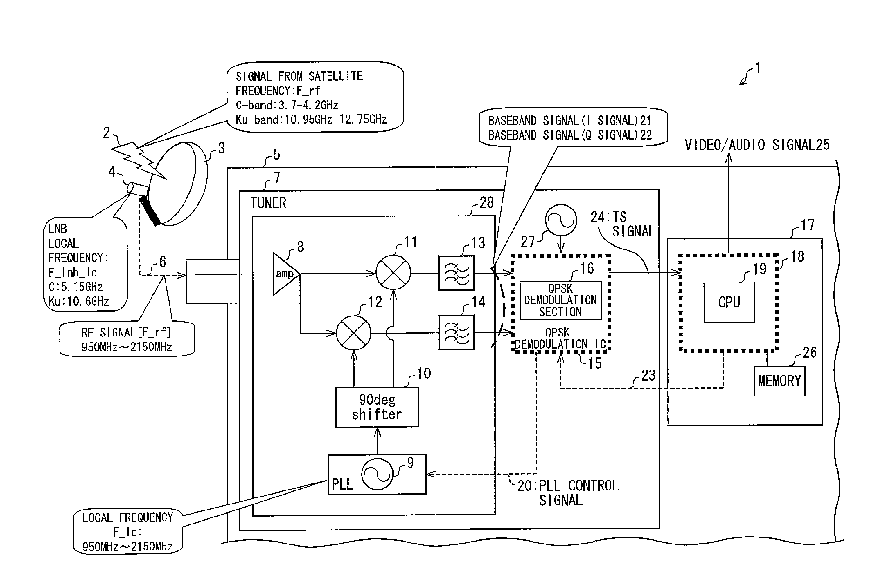
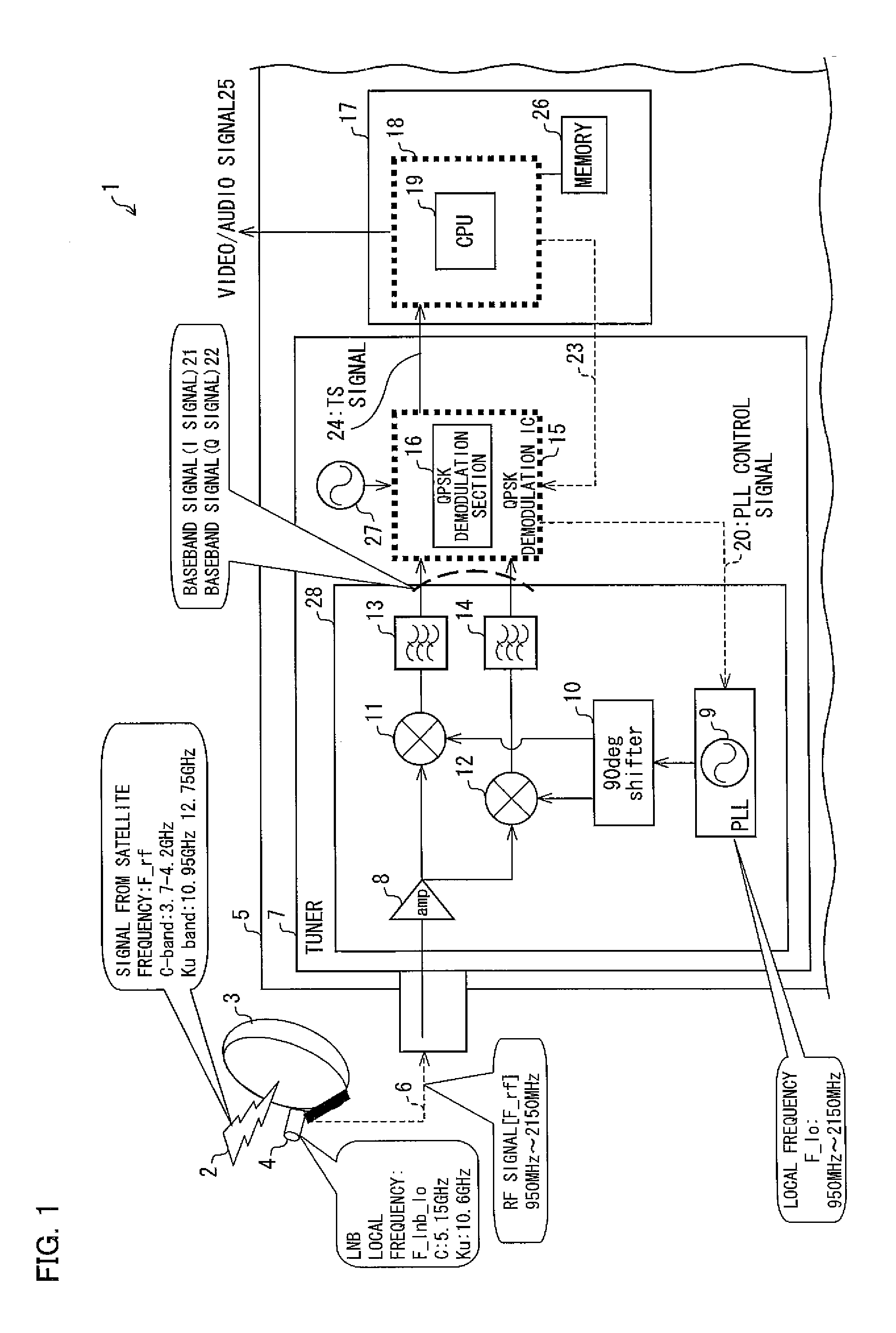
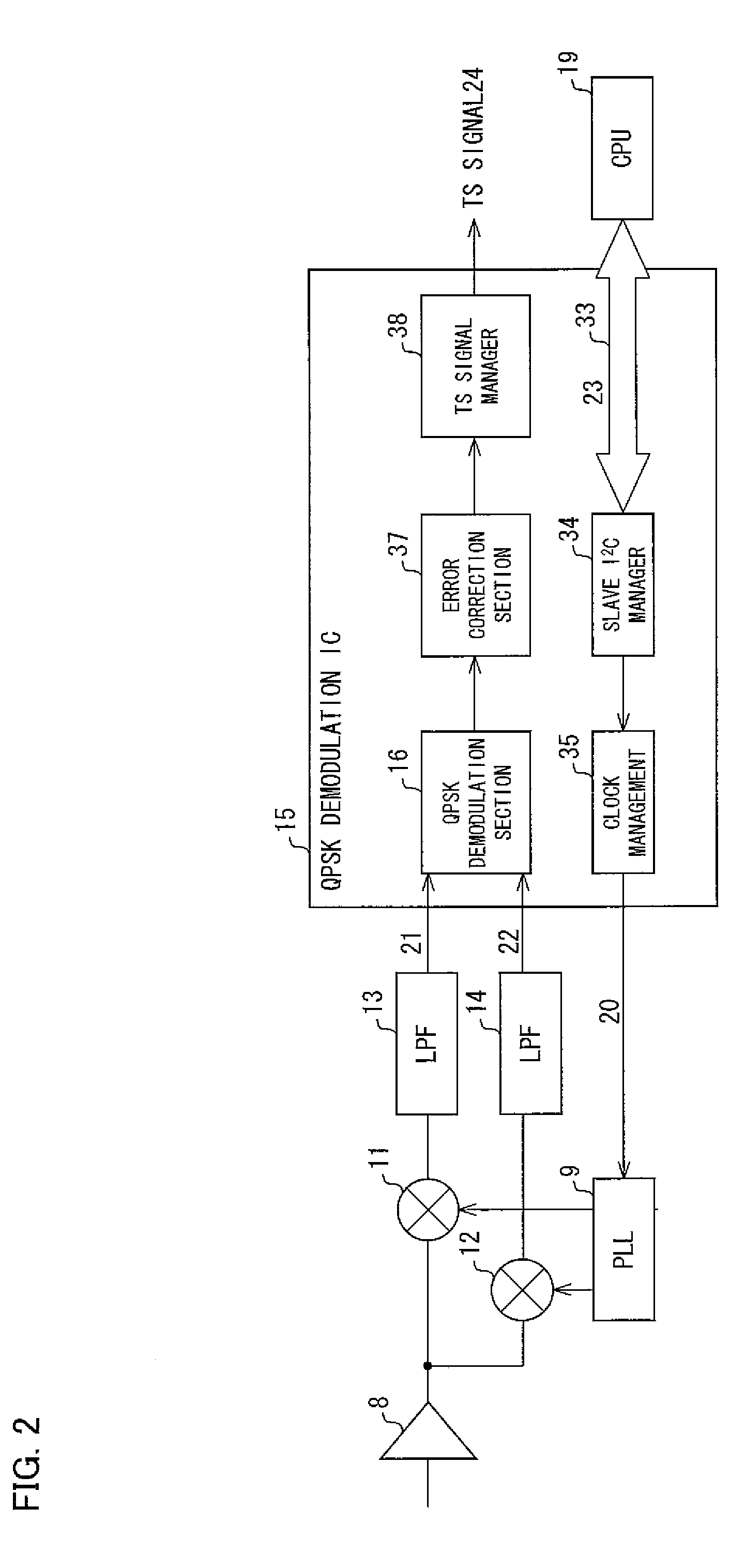
[0035]The following describes, with reference to FIG. 1 to FIG. 7, one embodiment of the present invention.

[0036]FIG. 1 is a block diagram illustrating a digital satellite broadcasting system 1 according to the present invention. A signal 2 transmitted from a satellite is received by a DISH antenna 3, and the frequency of the signal 2 thus received is converted by an LNB (Low Noise Block Converter) 4. The signal whose frequency has been thus converted is inputted to a satellite broadcasting receiving device 5. The satellite broadcasting receiving device 5 is, for example, a set top box (STB).

[0037]An RF signal 6 to be inputted to the satellite broadcasting receiving device 5 is inputted to a tuner 7. Then, the signal level of the RF signal 6 is adjusted by an AMP 8 included in the tuner 7. The RF signal whose signal level has been thus adjusted is converted into a baseband signal by: a PLL 9 for outputting a signal having a local frequency F_lo; a 90-degree phase shifter 10 for shif...


PUM


Abstract

When a satellite broadcasting receiving device 5 is initially set up, a receivable channel is searched for each satellite. In this search, a wider frequency acquisition range than a frequency acquisition range which is generally used is set for a QPSK demodulation IC 15, while the frequency of a PLL 9 is fixed. Then, in the wider frequency acquisition range, an offset is shifted by a frequency step Fstep′ by using a function for setting a frequency offset, the function being included in the QPSK demodulation IC 15. Thus, a signal search is carried out throughout a reception frequency range.

Description

[0001]This Nonprovisional application claims priority under U.S.C. §119(a) on Patent Application No. 278138 / 2007 filed in Japan on Oct. 25, 2007, the entire contents of which are hereby incorporated by reference.FIELD OF THE INVENTION[0002]The present invention relates to a digital satellite broadcasting receiving tuner and a satellite broadcasting receiving device including the same.BACKGROUND OF THE INVENTION[0003]FIG. 8 is a block diagram illustrating a conventional digital satellite broadcasting system 101. A signal 102 transmitted from a satellite is received by a DISH antenna 103, and the frequency of the signal 102 thus received is converted by an LNB (Low Noise Block Converter) 104. The signal whose frequency has been thus converted is inputted to a satellite broadcasting receiving device 105. The satellite broadcasting receiving device 105 is, for example, a set top box (STB). An RF (Radio Frequency) signal 106 to be inputted to the satellite broadcasting receiving device 1...

Claims


Application Information

Patent Timeline
IPC IPC(8): H04L27/22H03J7/18H04B1/16H04N5/44H04N7/20
CPCH03J7/18H04L27/2335H04L27/2332
Inventor IKEDA, HITOSHI
Owner SHARP KK
Learn More