Scroll compressor

Active Publication Date: 2009-04-30
LG ELECTRONICS INC
View PDF11 Cites 18 Cited by
  • Summary
  • Abstract
  • Description
  • Claims
  • Application Information

AI Technical Summary

Benefits of technology

[0008]Therefore, an object of the present invention is to provide a scroll compressor which is capable of modulating a capacity of the compressor using bypass holes, of reducing th

Problems solved by technology

However, in the related art, the manner using the bypass holes has the following problems.
Accordingly, a fabrication cost may increase.
And, since it is required to control the bypass holes disposed to be remote from each other at the same t

Method used


Image

  • Scroll compressor
  • Scroll compressor
  • Scroll compressor

Examples


Embodiment Construction

[0020]Hereafter, description will now be given in detail of one embodiment of a scroll compressor according to the present invention with accompanying drawings.

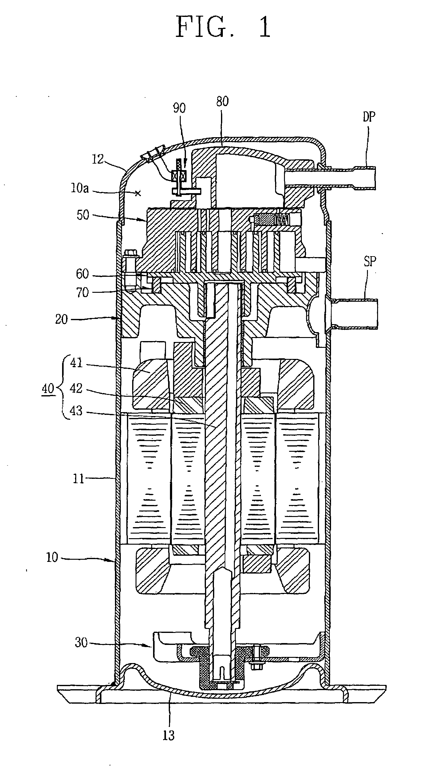
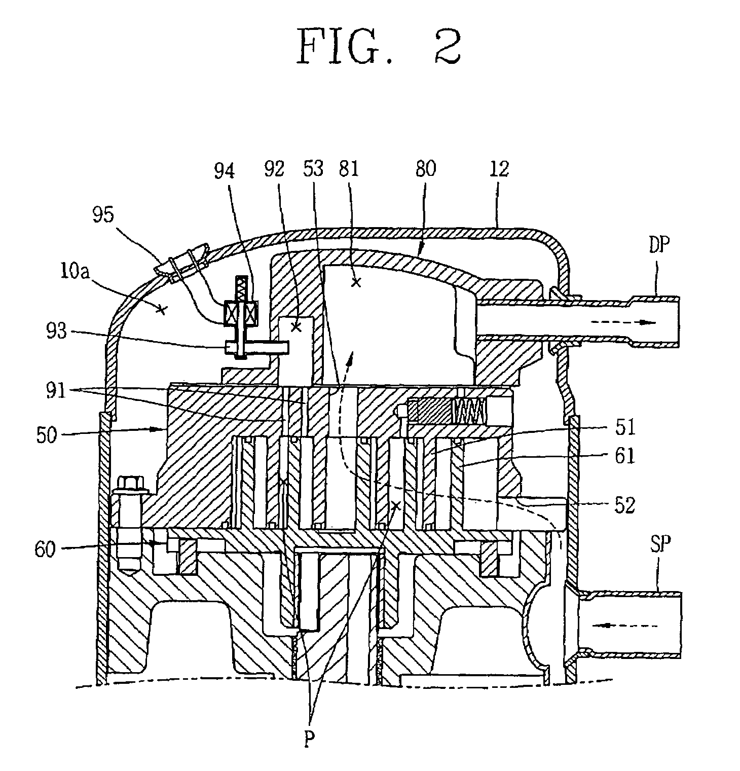
[0021]FIGS. 1 to 3 are cross section views showing one exemplary embodiment of a scroll compressor in accordance with the present invention.

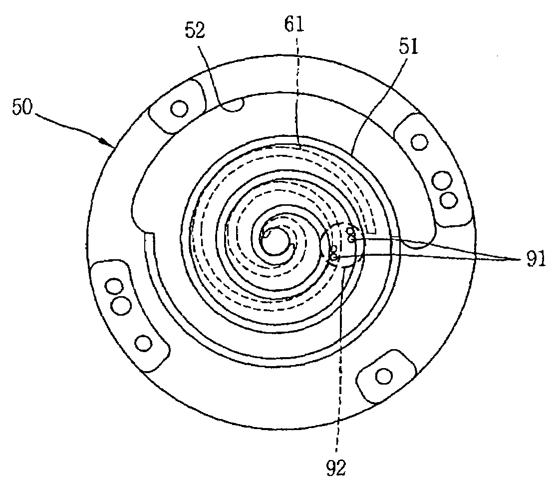
[0022]As shown in FIGS. 1 and 2, the scroll compressor in accordance with the present invention includes a hermetic container 10 provided with a gas suction pipe (SP) and a gas discharge pipe (DP), a main frame 20 and a sub frame 30 respectively fixed at upper and lower portions of the hermetic container 10, a driving motor 40 mounted between the main frame 20 and the sub frame 30 so as to generate a rotational force, a fixed scroll 50 fixed over the main frame 20, an orbiting scroll 60 orbitably disposed on the main frame 20 so as to form one pair of compression chambers (P) by being engaged with the fixed scroll 50, an Oldham's ring 70 interposed between the orbiting scroll 60 and the m...


PUM


Abstract

The present invention relates to a scroll compressor. The scroll compressor is configured to have bypass holes communicated with compression chambers so as to bypass a part of a compressed refrigerant and thus to modulate a capacity of the compressor, a middle pressure chamber and a valve. Accordingly, it is capable of simplifying a capacity modulation apparatus of the scroll compressor, thereby miniaturizing the compressor and reducing a fabrication cost. And, as the bypass holes are disposed to be adjacent to each other, an operating capacity of the compressor can be easily modulated with only one bypass valve, accordingly it is capable of reducing the number of bypass valve and of enhancing reliability.

Description

RELATED APPLICATION[0001]The present disclosure relates to subject matter contained in priority Korean Application No. 10-2007-0109830, filed on Oct. 30, 2007, which is herein expressly incorporated by reference in its entirety.BACKGROUND OF THE INVENTION[0002]1. Field of the Invention[0003]The present invention relates to a capacity modulation apparatus of a scroll compressor.[0004]2. Background of the Invention[0005]Generally, a scroll compressor is broadly used in an air conditioning system and has characteristics of high efficiency and low noise. The scroll compressor is implemented in a manner as follows. That is, two scrolls relatively orbit and then one pair of compression chambers are formed between the two scrolls. And, as the compression chambers continuously move toward a center, volume thereof is reduced. Accordingly, a refrigerant is consecutively sucked, compressed and discharged.[0006]In the related art scroll compressor, bypass holes are formed in the middle of the c...

Claims


Application Information

Patent Timeline
IPC IPC(8): F04B49/24F04C18/02
CPCF04C18/0215F04C18/0261F04C23/008F04C2240/806F04C28/26F04C2240/30F04C28/10F04C18/04
Inventor CHO, YONG-IL
Owner LG ELECTRONICS INC
Why Eureka
Try Eureka