Zoom lens, optical apparatus equipped with the zoom lens and method for forming an image of an object and varying a focal length

a zoom lens and optical apparatus technology, applied in the field of zoom lenses, can solve the problems of lager aperture, lens system failure to provide optical performance, lager aperture, etc., and achieve the effects of wide angle of view, high zoom ratio, and high imaging performan

Inactive Publication Date: 2009-05-07
NIKON CORP
View PDF5 Cites 33 Cited by
  • Summary
  • Abstract
  • Description
  • Claims
  • Application Information

AI Technical Summary

Benefits of technology

[0006]An embodiment of the present invention has been accomplished in view of the above-described problems and an object of an embodiment of the present invention is to provide a zoom lens capable of achieving high imaging performance while having a wide angle of view and a high zoom ratio, and an optical apparatus equipped with this zoom lens.
[0007]For purposes of summarizing an embodiment of the invention, certain aspects, advantag

Problems solved by technology

However, the light receiving elements in the increased number of pixels raised the problem that the conventional lens systems failed to provide optical performance compatible with a wider light reception area and the problem that the lens system tended to become larger in order to achieve a lager aperture.
As the len

Method used


Image

  • Zoom lens, optical apparatus equipped with the zoom lens and method for forming an image of an object and varying a focal length
  • Zoom lens, optical apparatus equipped with the zoom lens and method for forming an image of an object and varying a focal length
  • Zoom lens, optical apparatus equipped with the zoom lens and method for forming an image of an object and varying a focal length

Examples


embodiments

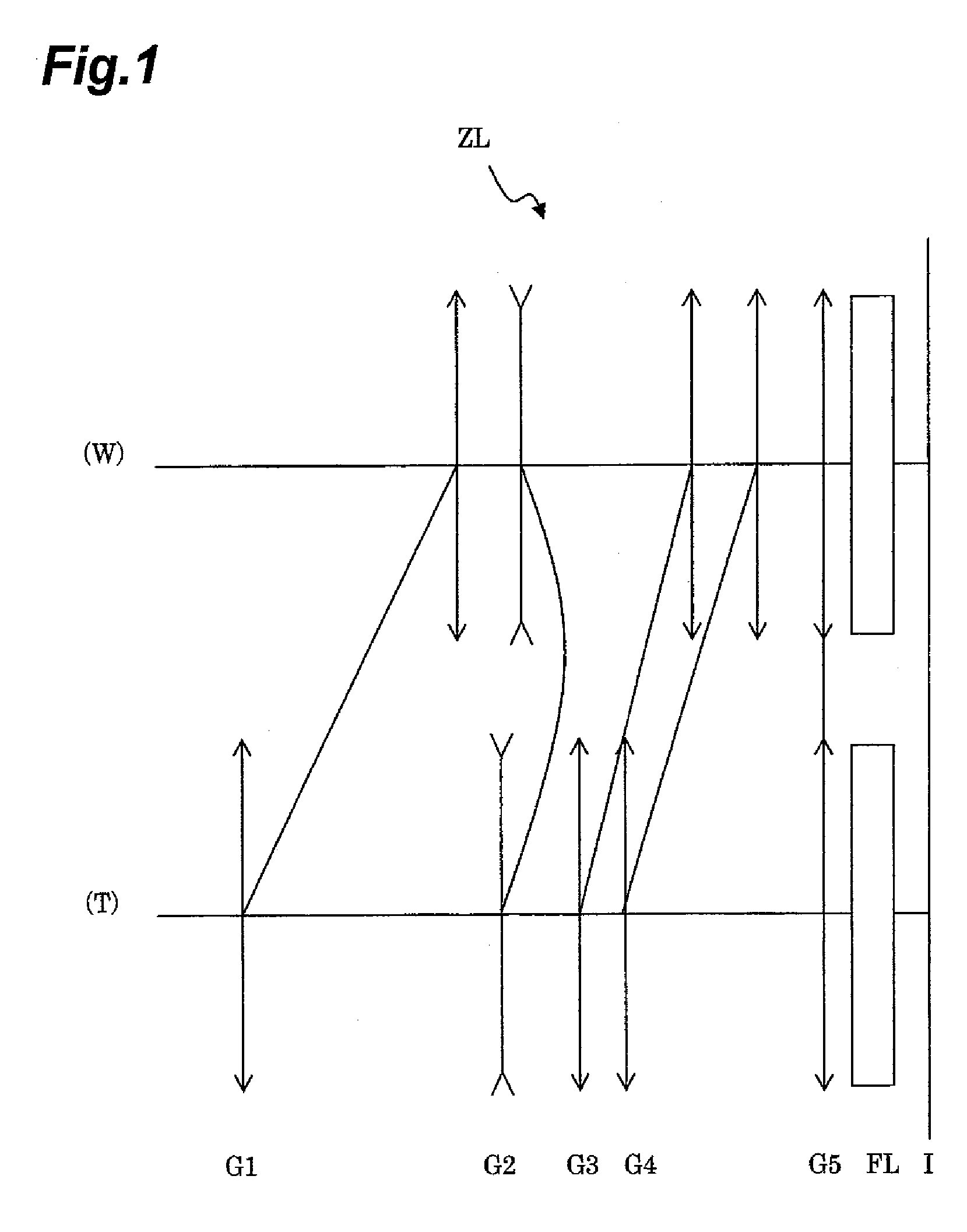
[0087]Each of embodiments of the present invention will be described below on the basis of the accompanying drawings. FIG. 1 is a drawing showing a refracting power layout of a zoom lens ZL according to the present embodiment and a state of movement of each of lens groups with a change in the focal length state from the wide-angle end state (W) to the telephoto end state (T). As shown in this FIG. 1, the zoom lens ZL of the present embodiment is composed of the following components in the order from the object side: a first lens group G1 having a positive refracting power; a second lens group G2 having a negative refracting power; a third lens group G3 having a positive refracting power; a fourth lens group G4 having a positive refracting power; a fifth lens group G5 having a positive refracting power; and a filter group FL consisting of a low-pass filter, an infrared cut filter, and so on. With the change in the focal length state from the wide-angle end state to the telephoto end ...

first embodiment

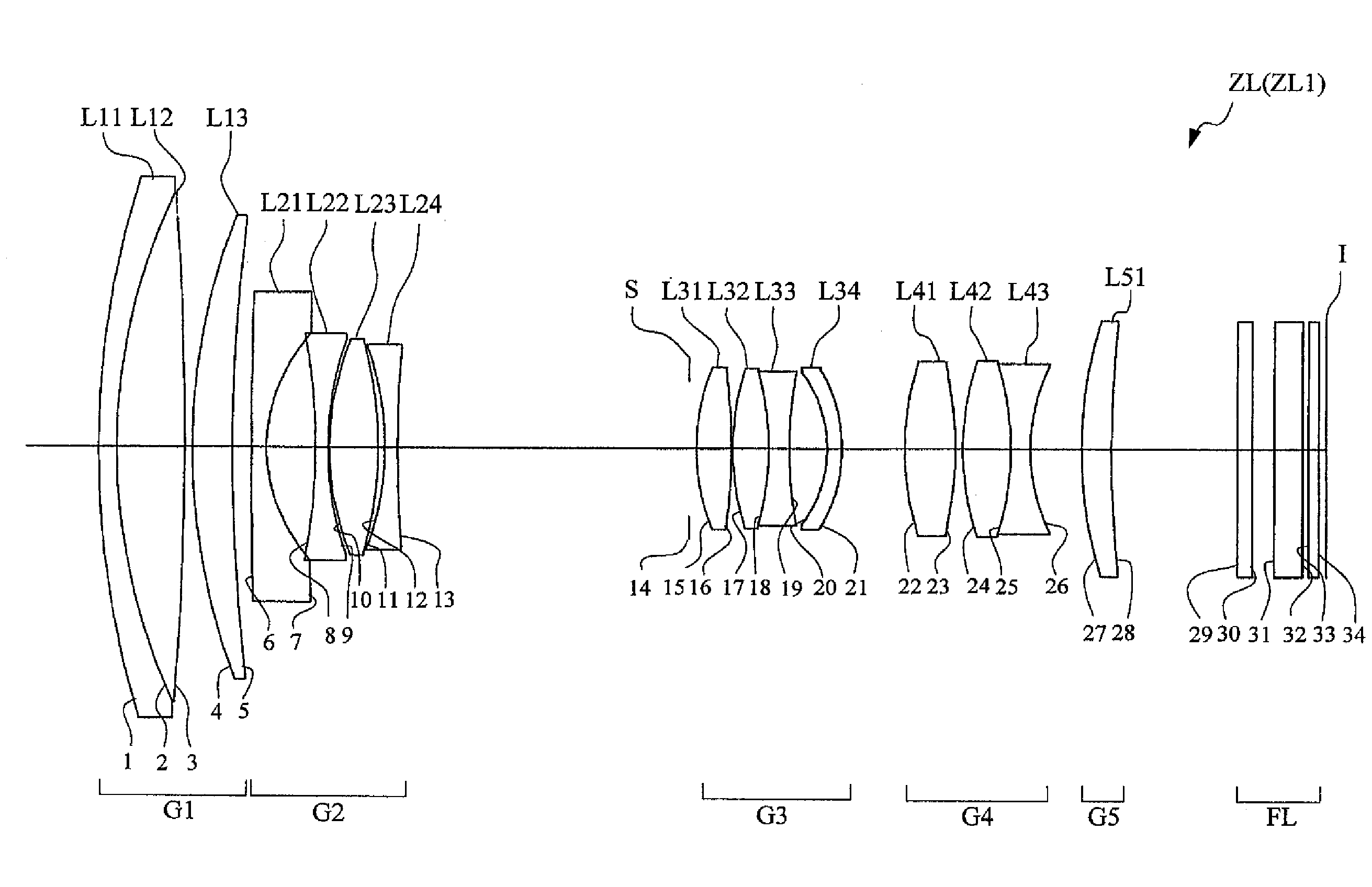
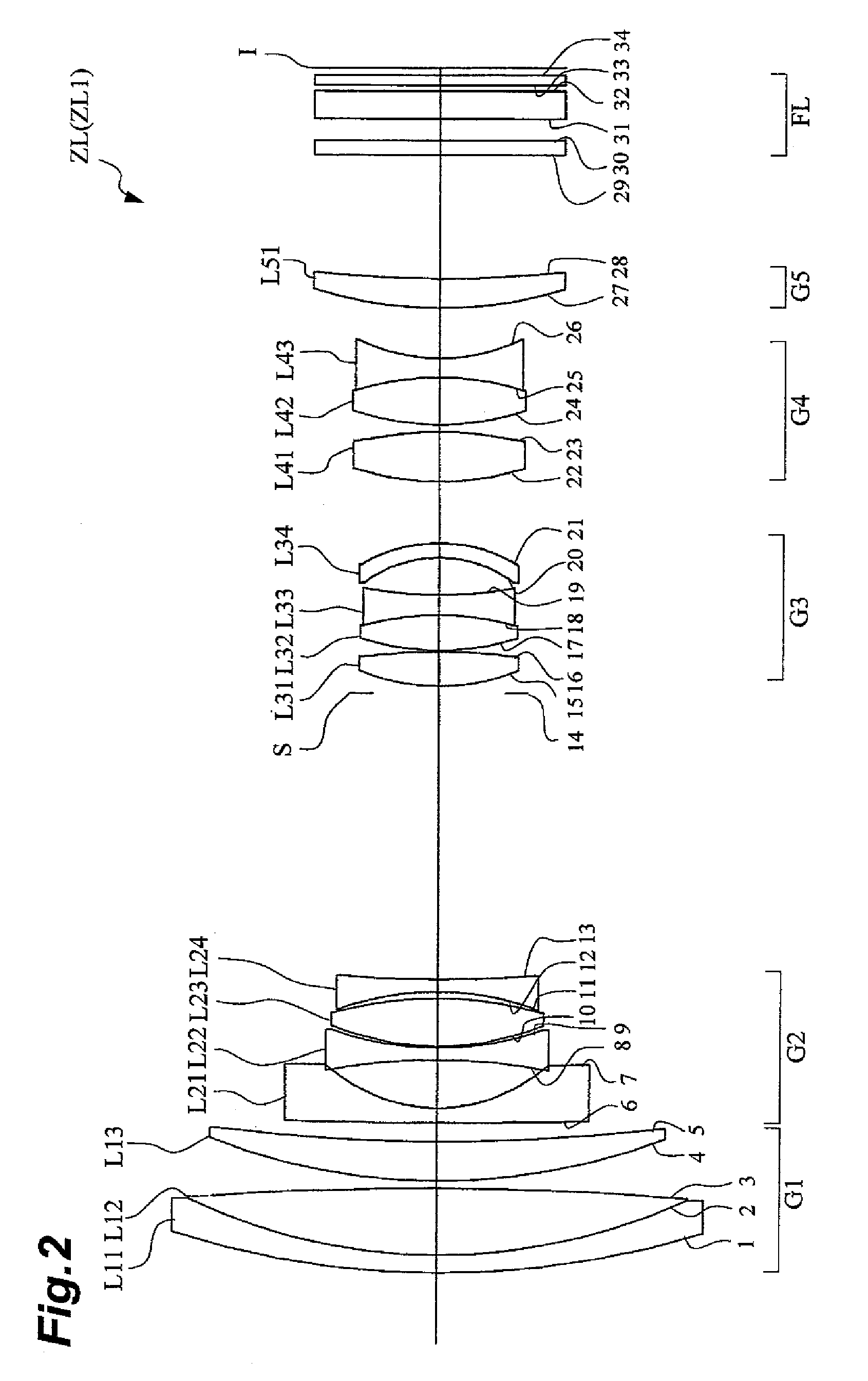
[0090]FIG. 2 is a drawing showing a configuration of a zoom lens ZL1 according to the first embodiment of the present invention. In this zoom lens ZL1 of FIG. 2, the first lens group G1 is composed of a cemented positive lens consisting of a negative meniscus lens L11 with a convex surface on the object side and a biconvex lens L12 cemented together, and a positive meniscus lens L13 with a convex surface on the object side, which are arranged in the order from the object side. The second lens group G2 is composed of a negative meniscus lens L21 with an aspherical surface on the image side and a convex surface on the object side, a biconcave lens L22, a biconvex lens L23, and a biconcave lens L24, which are arranged in the order from the object side. The third lens group G3 is composed of a biconvex lens L31, a cemented negative lens consisting of a biconvex lens L32 and a biconcave lens L33 cemented together, and a negative meniscus lens L34 with an aspherical surface on the image s...

second embodiment

[0098]FIG. 5 is a drawing showing a configuration of a zoom lens ZL2 according to the second embodiment of the present invention. In this zoom lens ZL2 of FIG. 5, the first lens group G1 is composed of a cemented positive lens consisting of a negative meniscus lens L11 with a convex surface on the object side and a biconvex lens L12 cemented together, and a positive meniscus lens L13 with a convex surface on the object side, which are arranged in the order from the object side. The second lens group G2 is composed of a negative meniscus lens L21 with an aspherical surface on the image side and a convex surface on the object side, a biconcave lens L22, a biconvex lens L23, and a biconcave lens L24, which are arranged in the order from the object side. The third lens group G3 is composed of a biconvex lens L31, a cemented negative lens consisting of a biconvex lens L32 and a biconcave lens L33 cemented together, and a negative meniscus lens L34 with an aspherical surface on the image ...


PUM


Abstract

A zoom lens comprises the following lens groups in the order from an object side: a first lens group having a positive refracting power; a second lens group having a negative refracting power; a third lens group having a positive refracting power; and a fourth lens group having a positive refracting power; wherein, upon zooming, at least the first lens group and the fourth lens group move to the object side; and wherein the third lens group comprises a negative meniscus lens with a convex surface on an image side and with both side faces thereof being exposed to air, which is located nearest to the image side.

Description

BACKGROUND OF THE INVENTION[0001]1. Field of the Invention[0002]The present invention relates to a zoom lens.[0003]2. Related Background Art[0004]There is a conventionally known zoom lens of a positive, negative, positive, positive, and positive 5-group type. This zoom lens of the positive, negative, positive, positive, and positive 5-group type is composed of the following five lens groups arranged in the order from the object side: a first lens group having a positive refracting power; a second lens group having a negative refracting power; a third lens group having a positive refracting power; a fourth lens group having a positive refracting power; and a fifth lens group having a positive refracting power, and is configured so that, with a change in a lens position state from a wide-angle end state (a state in which the focal length is the shortest) to a telephoto end state (a state in which the focal length is the longest), at least the first lens group and the third lens group ...

Claims


Application Information

Patent Timeline
IPC IPC(8): G02B15/20G02B15/16
CPCG02B15/173G02B15/145129
Inventor TAKE, TOSHINORI
Owner NIKON CORP
Why Eureka
Try Eureka