Eureka AIR delivers breakthrough ideas for toughest innovation challenges, trusted by R&D personnel around the world.

Construction apparatus

Inactive Publication Date: 2009-05-14
FRED PIERCE ENTERPRISES
View PDF12 Cites 2 Cited by
  • Summary
  • Abstract
  • Description
  • Claims
  • Application Information

AI Technical Summary

Benefits of technology

[0011]Therefore, it is an object of the present invention to provide an improved construction apparatus having particular utility when employed in new construction as well as when installed thereafter.
[0014]Another object is to provide such a construction apparatus which is particularly well suited to use in the construction of homes and other structures where it is desired to require a minimal period of time for installation and completion and so as similarly to reduce the labor expenses required therefore.
[0016]Another object is to provide such a construction apparatus which substantially avoids the need for frequent adjustment and repair such as required by prior art devices employed for the same or similar purposes.
[0017]Another object is to provide such a construction apparatus having particular utility in combining the benefits of at least two uses in a single device which, in such use, complement each other so as to require a minimum amount of space and convenience of use while having an ease and dependability of operation.
[0019]Another object is to provide such a construction apparatus which can be manufactured and sold at less cost than has heretofore been possible with prior art devices intended for similar purposes.
[0020]Further objects and advantages are to provide improved elements and arrangements thereof in an apparatus for the purpose described which is dependable, economical, durable and fully effective in accomplishing its intended purposes.

Problems solved by technology

In many environments, there are competing considerations which tend to be in conflict during installation of a work object or the like and the subsequent use thereof.
For example, in the construction industry the cost of the product, the ease of installation, the labor expenses, the precision of construction and dependability in use, among others, are often in direct conflict.
Unfortunately, success in these regards has proved elusive and this dichotomy continues to exist.
The high visibility, frequency of use and reliance thereon reveals such undesirable characteristics.
However, in conventional construction such assemblies are difficult to install.
They are, consequently, often improperly installed by construction workers.
In this event, they cannot be operated as designed and intended.
Where properly installed, such structures readily fail during use so as to require frequent adjustment, repair, replacement of parts and other attention.
In any case, such conventional assemblies are unsatisfactory in many respects.

Method used


Image

  • Construction apparatus
  • Construction apparatus
  • Construction apparatus

Examples


Embodiment Construction

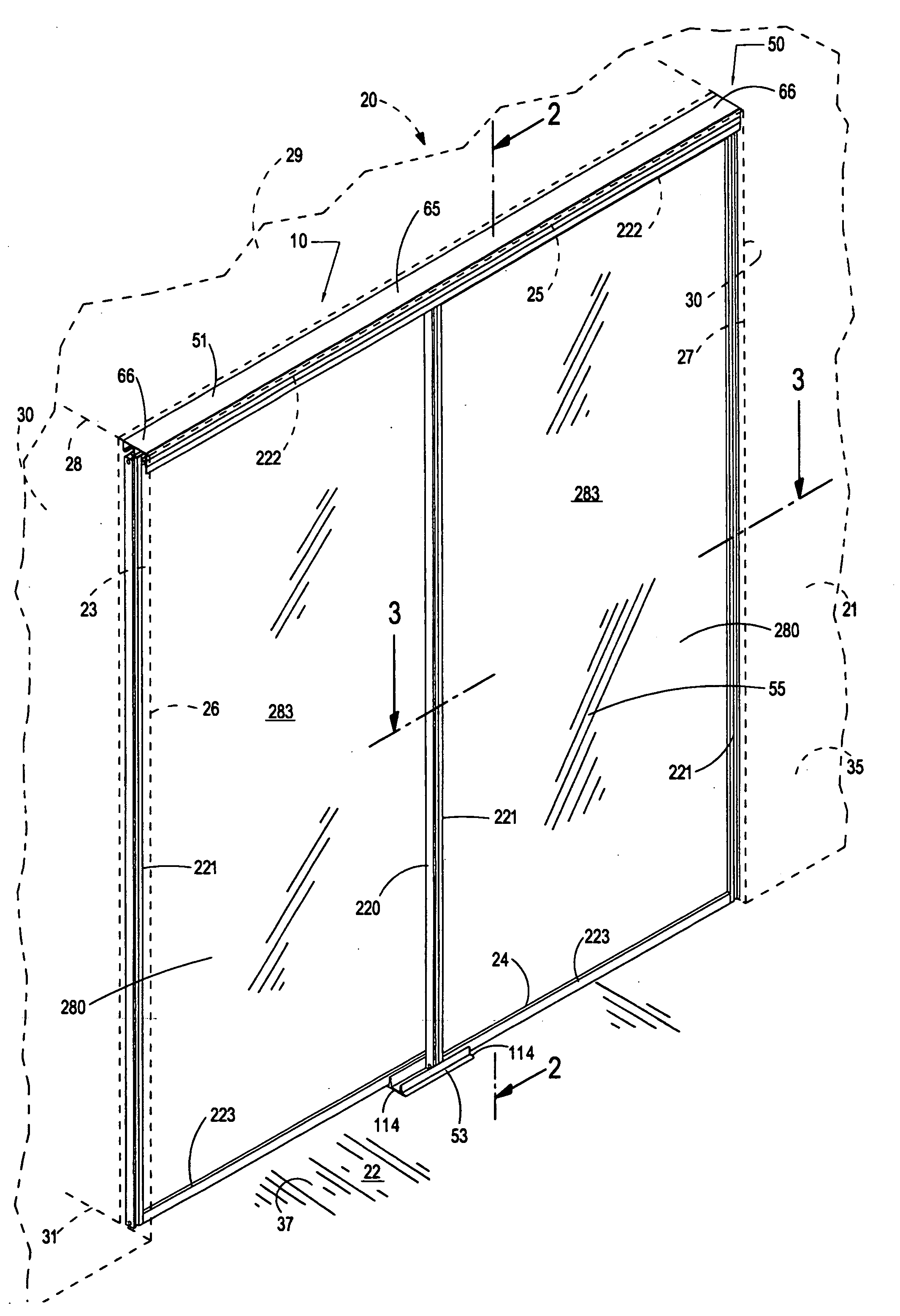
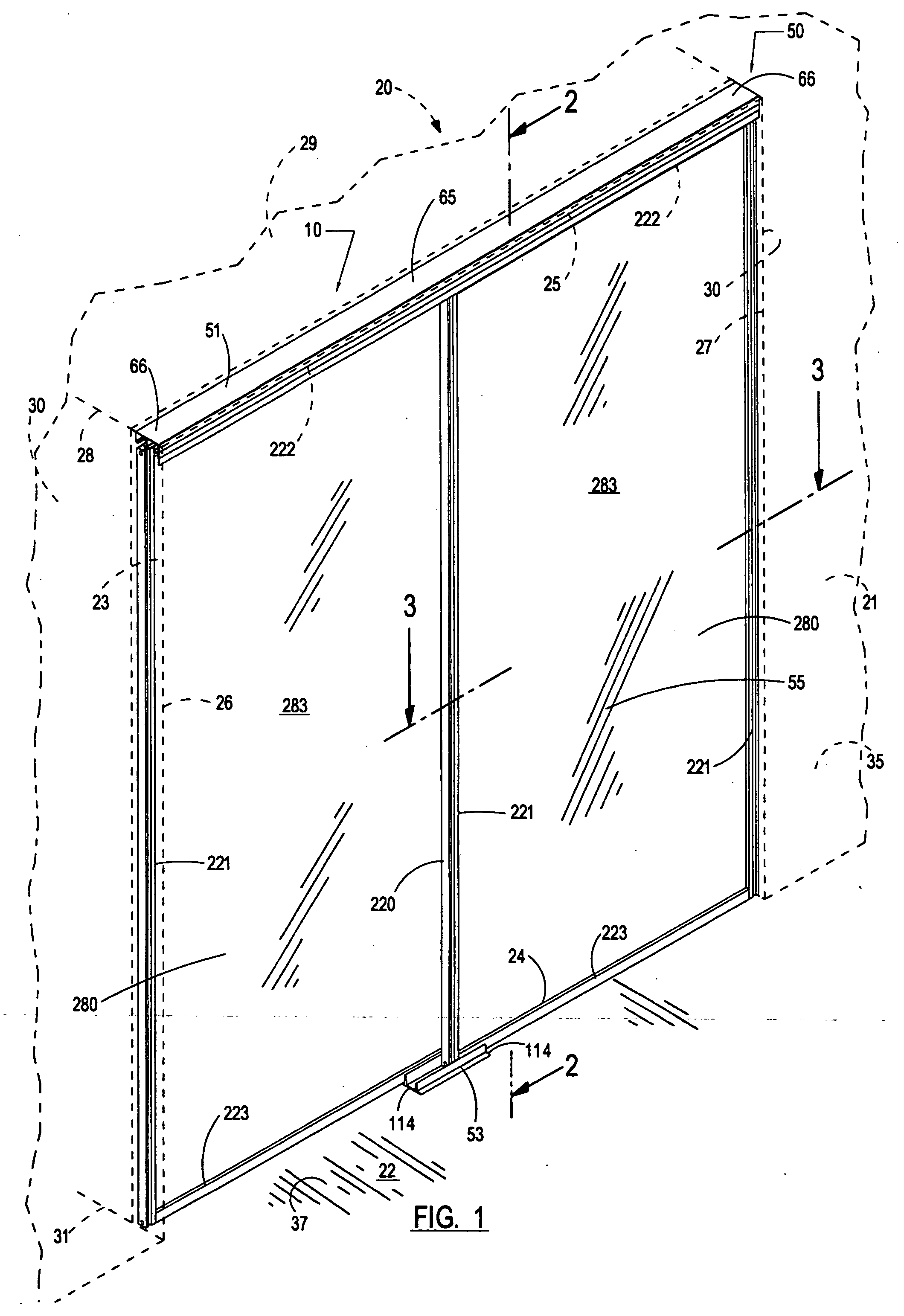
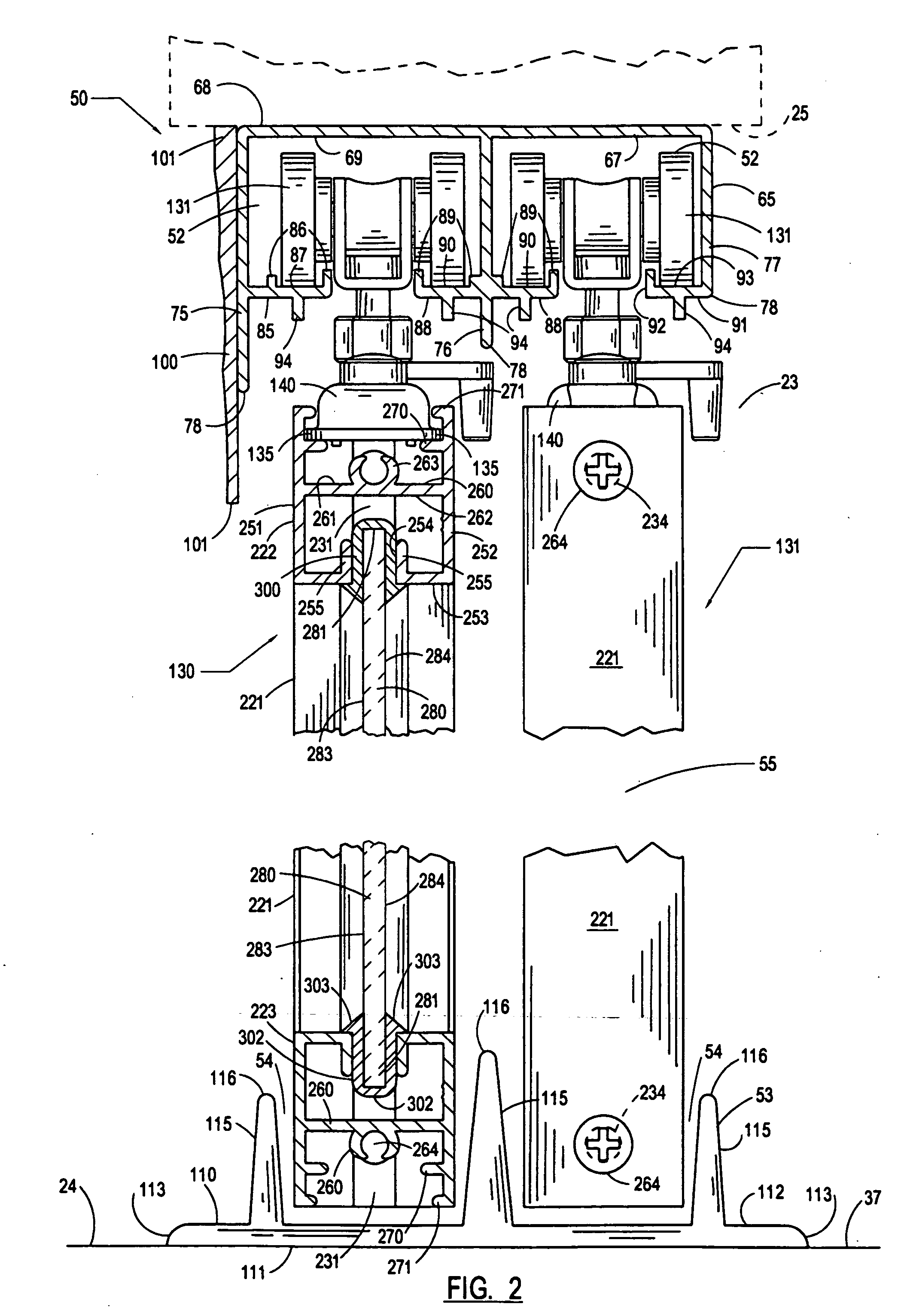
[0029]Referring more particularly to the drawings, the construction apparatus of the present invention is generally indicated by the numeral 10 in FIG. 1.

[0030]The construction apparatus 10 is adapted for use in a variety of environments. A representative operative environment is shown is the drawings and described herein. The operative environment is a structure generally indicated by the numeral 20 in FIG. 1. The structure can be visualized as being a house which is under construction. The structure has a substantially vertical wall 21 which can be visualized as an interior wall of the structure. The structure has a substantially horizontal floor 22. A substantially rectangular wall opening 23 extends through the wall oriented along a path which is substantially right-angularly related to the wall.

[0031]The wall opening 23 has a bottom side surface 24 and a top side surface 25 which is substantially parallel to the bottom side surface. The wall opening has a left side 26 and a rig...


PUM


Abstract

A construction apparatus having a frame adapted to be mounted on a support; at least one work object, having a predetermined upper portion and a lower portion; and an assembly mounting the work object in supported relation on the frame by the upper portion or the lower portion of the work object for substantially lateral movement relative to the support in the performance of a work operation.

Description

CROSS-REFERENCE TO RELATED APPLICATIONS[0001]Not applicable.STATEMENT REGARDING FEDERALLY SPONSORED RESEARCH OR DEVELOPMENT[0002]Not Applicable.BACKGROUND OF THE INVENTION[0003](1) Field of the Invention[0004]The present invention relates to a construction apparatus and, more particularly, to a construction apparatus which is unusually well suited to use in those environments in which the capability for installation at a rapid pace while providing a precision of operation and dependability of use are of substantial importance.[0005](2) Description of the Prior Art[0006]In many environments, there are competing considerations which tend to be in conflict during installation of a work object or the like and the subsequent use thereof. For example, in the construction industry the cost of the product, the ease of installation, the labor expenses, the precision of construction and dependability in use, among others, are often in direct conflict. In fact, in a relative sense, conventiona...

Claims


Application Information

Patent Timeline
IPC IPC(8): E05D15/08
CPCE05D15/063E05Y2600/52E05Y2201/64E05D15/08
Inventor VINCENT, BRENT DAVID
Owner FRED PIERCE ENTERPRISES
Why Eureka
Eureka Blog
Learn More