
Built-in battery assembly and a method of assembling the built-in battery with a circuit board

a built-in battery and circuit board technology, applied in the direction of secondary cells, non-printed electric components of printed circuits, cell components, etc., can solve the problems of increasing the overall cost of portable electronic devices, not only occupying space, and significantly affecting assembly efficiency

Inactive Publication Date: 2009-05-14
CHI MEI COMM SYST INC
View PDF17 Cites 3 Cited by
  • Summary
  • Abstract
  • Description
  • Claims
  • Application Information

AI Technical Summary

Benefits of technology

[0005]Conventional built-in batteries have positive and negative poles, and the output end of the positive and negative poles are drawn out via two leading wires welded thereon. In addition, a connector is applied for electrically connecting the built-in battery and a circuit board together to supply power to the portable electronic devices. However, the connector not only takes up space, but also increases overall cost of the portable electronic devices. Further, according to typical manufacturing process, the two leading wires are manually welded, thereby significantly affecting assembly efficiency. Moreover, the above welding process may damage electronic elements or antennas arranged within the portable electronic devices, thereby affecting the performance of the portable electronic devices.

Problems solved by technology

However, the connector not only takes up space, but also increases overall cost of the portable electronic devices.
Further, according to typical manufacturing process, the two leading wires are manually welded, thereby significantly affecting assembly efficiency.
Moreover, the above welding process may damage electronic elements or antennas arranged within the portable electronic devices, thereby affecting the performance of the portable electronic devices.

Method used


Image

  • Built-in battery assembly and a method of assembling the built-in battery with a circuit board
  • Built-in battery assembly and a method of assembling the built-in battery with a circuit board
  • Built-in battery assembly and a method of assembling the built-in battery with a circuit board

Examples


Embodiment Construction

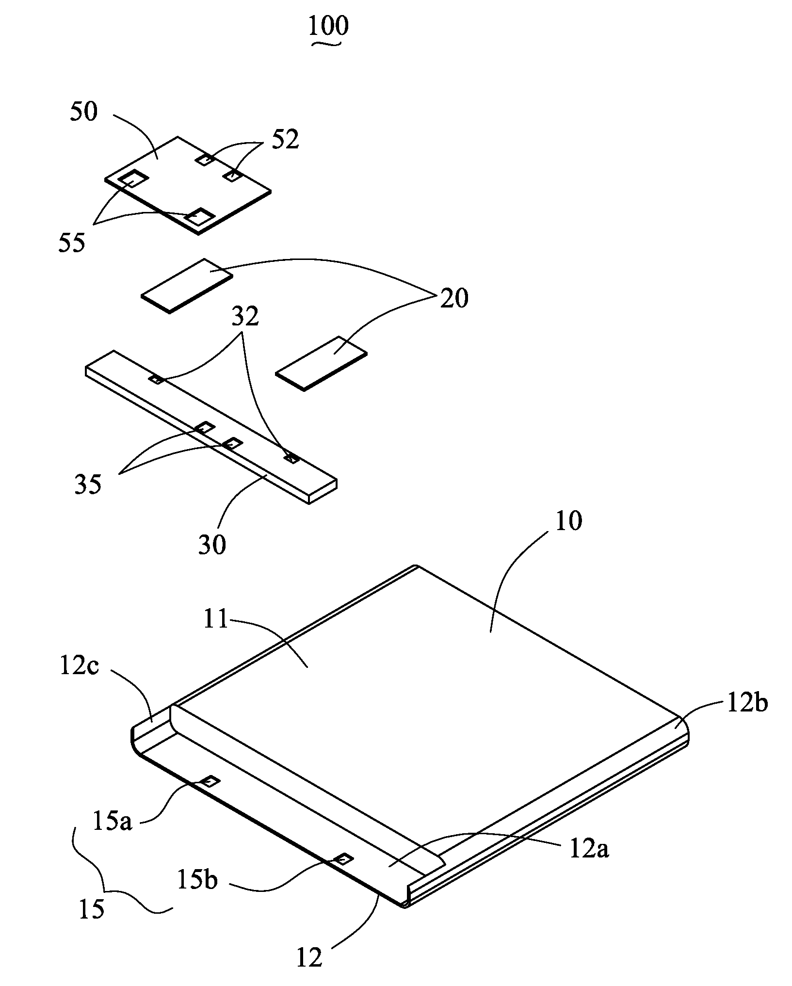
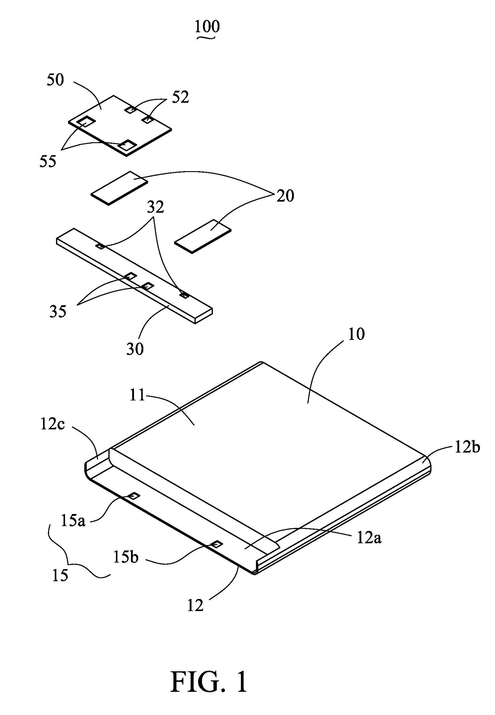
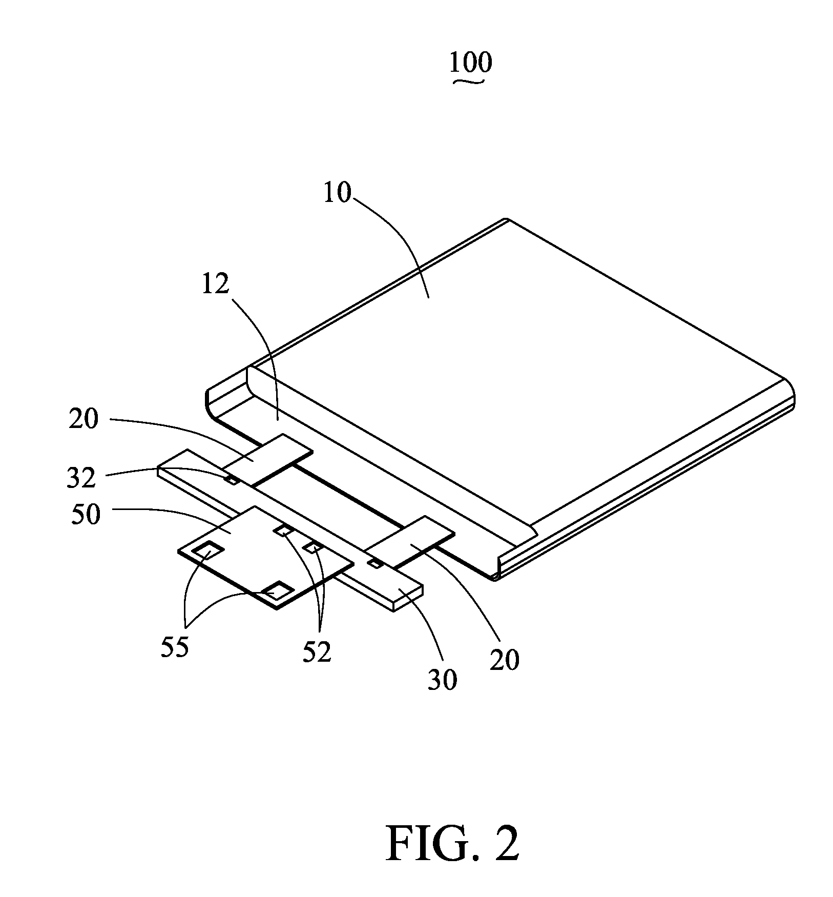
[0014]FIG. 1 shows an exemplary embodiment of a built-in battery assembly 100 including a battery body 10, two connecting strips 20, a protective circuit board 30 and a flexible connecting board 50. The battery body 10 is substantially rectangular-shaped and includes a main body 11, a receiving portion 12, and a positive pole 15a and a negative pole 15b. The main body 11 is substantially rectangular-shaped. The receiving portion 12 is formed by a base 12a and two vertical opposite sides 12b, 12c. As shown in FIG. 1, the receiving portion 12 has a U-shaped cross-section. The main body 11 may be arranged within the receiving portion 12. The positive pole 15a and the negative pole 15b of the battery body 10, which are spaced from each other, are associated with the base 12a of the receiving portion 12.

[0015]The two connecting strips 20 are made of flexible conductive material. Referring to FIG. 2, each connecting strip 20 electrically connects one of the positive pole 15a and the negat...


PUM

PropertyMeasurementUnit
Angleaaaaaaaaaa
Flexibilityaaaaaaaaaa
Electrical conductoraaaaaaaaaa

Abstract

A built-in battery assembly (100) including a battery body (10) and a flexible connecting board (50) is described. The flexible connecting board includes a first pair of terminals (52) and a second pair of terminals (55), wherein the first pair of terminals electrically connects to the battery body and the second pair of terminals protrudes from the battery body. In addition, a method of assembling the built-in battery assembly to a circuit board (80) is also described.

Description

BACKGROUND OF THE INVENTION[0001]1. Field of the Invention[0002]The present invention generally relates to built-in batteries and, particularly, to built-in batteries arranged within a portable electronic device and a method of assembling the built-in battery assembly to a circuit board of the portable electronic device.[0003]2. Discussion of the Related Art[0004]With rapid development of communication, portable electronic devices, such as cellular phones, personal digital assistant (PDA), and so on, have become more and more popular. Generally, the portable electronic devices are equipped with detachable batteries. However, as the demand for light and small portable electronic devices increases, built-in batteries are provided that reduce the required internal space for electronic elements in the portable electronic devices.[0005]Conventional built-in batteries have positive and negative poles, and the output end of the positive and negative poles are drawn out via two leading wire...

Claims


Application Information

Patent Timeline
IPC IPC(8): H05K1/16H05K1/00H05K3/30H01M50/247H01M50/298H01M50/516H01M50/572
CPCH01M2/0404H01M10/425Y10T29/4913H05K1/148H05K2201/10037H05K1/147Y02E60/10
Inventor CHANG, MING-SHIUNG
Owner CHI MEI COMM SYST INC
Learn More