Developing roller, developing apparatus using the same, and image forming apparatus

a technology of developing rollers and developing apparatuses, applied in electrographic process apparatus, instruments, optics, etc., can solve the problems of reducing the number of rollers fused with the deteriorated developer on the surface, increasing the number of developing rollers and controlling members, and increasing the risk of deterioration of developers. , to achieve the effect of high image quality

Inactive Publication Date: 2009-05-14
CANON KK
View PDF20 Cites 6 Cited by
  • Summary
  • Abstract
  • Description
  • Claims
  • Application Information

AI Technical Summary

Benefits of technology

[0014]An object of the present invention is to provide a developing roller improved in the fog and the resulting stripe from development at the continuous printing time, and moreover, to provide a developing apparatus and an image forming apparatus of high image quality using such a developing roller.
[0015]As a result of repeated examinations on an elastic resin particle added in the surface layer of the developing roller and the surface state, the present inventor and others have found that a developing roller, a developing apparatus, and an image forming apparatus capable of achieving the above described objects can be obtained.
[0020]According to the present invention, a developing roller can be provided in which a fog and a resulting stripe from development at the continuous printing are improved, and a developing apparatus and an image forming apparatus capable of stably forming a high quality image can be provided.

Problems solved by technology

However, much needs to be improved in a specific image quality item, particularly, a fog and a stripe-like image defect (hereinafter, referred to as resulting stripe from development) at the continuous printing time.
That is, when the developer is made into an extremely small particle, the number of contacts / collisions of the fellow developers or the developer with the developing roller and the developer controlling member is increased, and the developer is liable to deteriorate.
The developing roller fused with the deteriorated developer on the surface is reduced in the charge imparting amount to the developer, and as a result, the fog is often generated in the electrophotographic image.
Further, when the deteriorated developer is partially fused on the surface of the developer controlling member, a coating amount of the developer on the developing roller is liable to be non-uniform.
That is, the application of the bias on the developing blade increases a stress given to the developer, and the fusion of the developer and an external additive of the developer on the developing roller surface and the developing blade easily generate the fog and the resulting stripe from development.

Method used


Image

  • Developing roller, developing apparatus using the same, and image forming apparatus
  • Developing roller, developing apparatus using the same, and image forming apparatus
  • Developing roller, developing apparatus using the same, and image forming apparatus

Examples


embodiments

[0174]Hereinafter, while the present invention will be described by using embodiments and comparative examples in details, but the present embodiment does not limit the present invention.

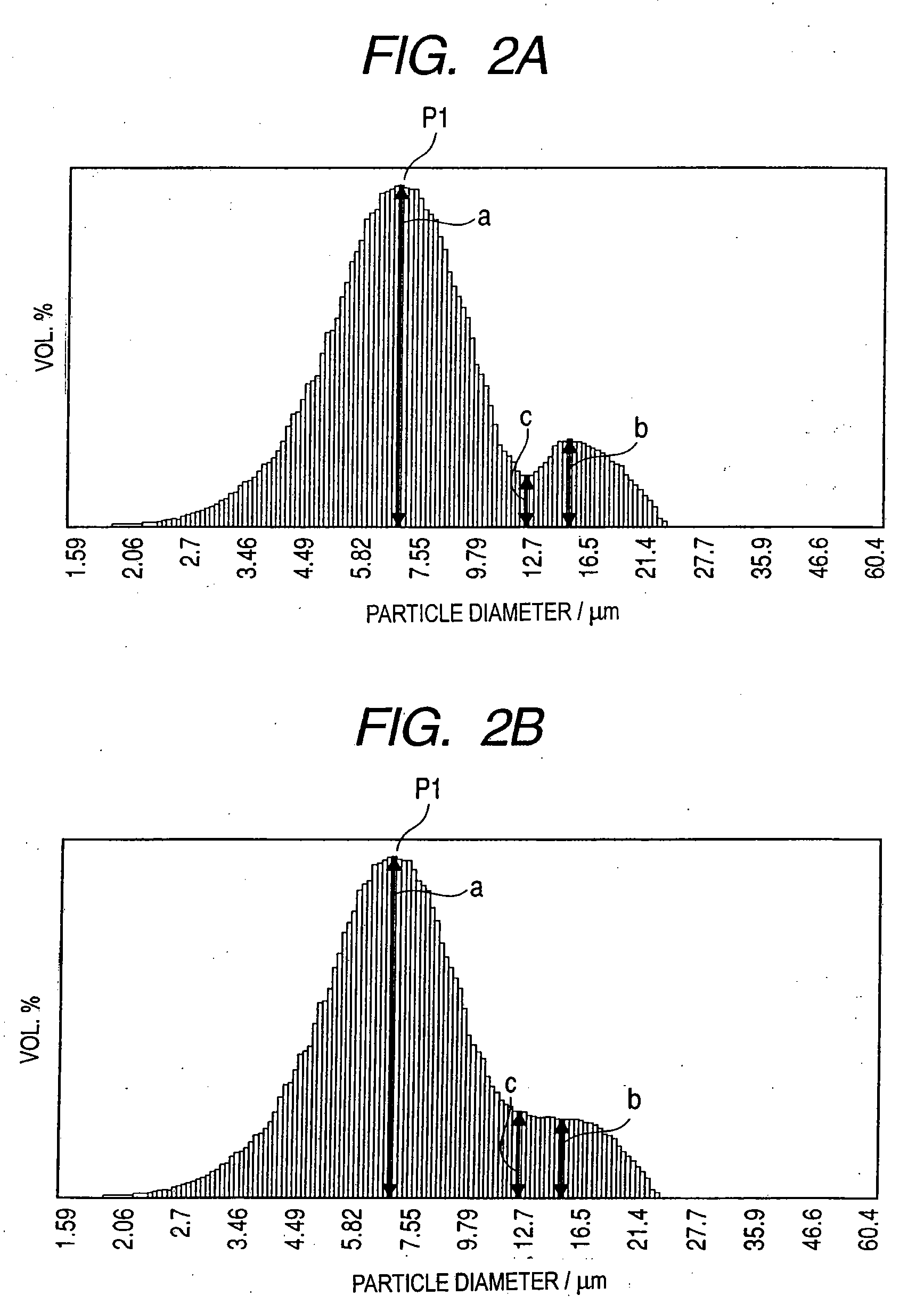
[0175]Kinds of the resin particles used in each embodiment and each comparative example are as follows. It is to be noted that the volume average particle diameter of each resin particle is a measurement value by the precision particle size distribution measurement device (Product name: Multisizer 2; made by Beckman Coulter, Inc.).

[0176](Resin Particle A)

[0177]A urethane resin particle (Product name: Art Pearl C800 transparent; made by Negami Chemical Industrial Co. Ltd., the volume average particle diameter 7.3 μm).

[0178](Resin Particle B)

[0179]A urethane resin particle (Product name: Art Pearl C600 transparent; made by Negami Chemical Industrial Co. Ltd., the volume average particle diameter 10.3 μm).

[0180](Resin Particle C)

[0181]A urethane resin particle (Product name: Art Pearl C400 transparent;...

example 1

Preparation of Developing Roller

[0220](Formation of Elastic Layer)

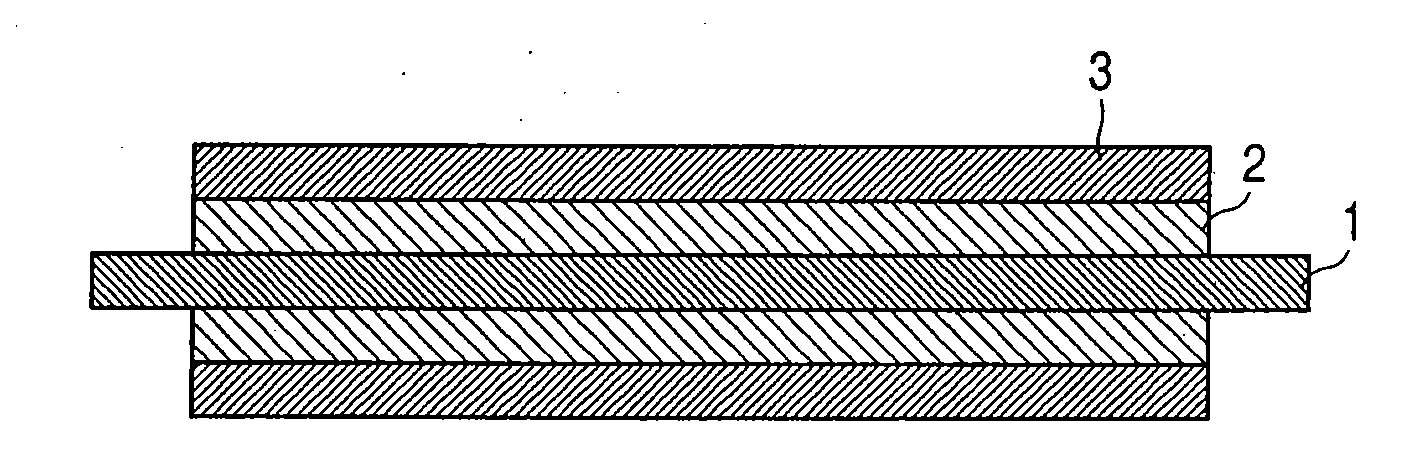
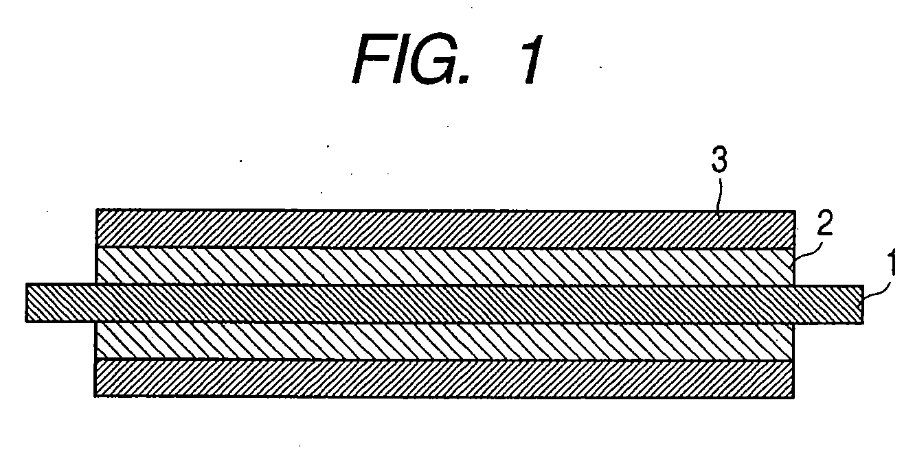
[0221]The surface of the cored bar made of SUS of 8 mm in diameter nickel-plated, and further coated and baked with PRIMER (Product name: DY35-051; made by Dow Corning Toray Silicon Co Ltd.) was prepared as a mandrel 1.

[0222]The mandrel 1 was disposed inside a cylindrical mold of 16 mm in inner diameter so as to be coaxial with the cylindrical mold. Next, an addition silicone rubber composition of the following composition was injected into the mold. Subsequently, the mold was heated, and the addition silicone rubber composition was vulcanized and hardened for 15 minutes at the temperature 150° C. After removing the hardened silicone rubber from the mold, the silicone rubber was further heated for two hours at the temperature 200° C., thereby completing a hardening reaction. The elastic layer 2 made of silicone rubber of 4 mm in thickness was disposed on the outer periphery of the mandrel 1.

[0223]

[0224]Liquid silicone...


PUM


Abstract

A developing roller having an elastic layer on the outer periphery of a mandrel and having a surface layer containing a resin and resin particles on its outer periphery, wherein the surface layer has a convex portion attributable to the resin particles, and has a surface of roughness in which a distortion degree Rsk of a roughness curve is 0.15 or more and 0.70 or less, wherein the resin particles have a peak P1 at a particle diameter dl in a volume particle size distribution, and wherein “a”, “b”, “c”, d1, d2 and d3 satisfy a specific relationship, where, “a” denotes a volume fraction of the resin particle having the particle diameter dl in the volume particle size distribution, and “b” and “c” denote volume fractions at particle diameters d2 and d3 respectively in the volume particle size distribution.

Description

[0001]This application is a continuation of International Application No. PCT / JP2007 / 068004, filed Sep. 10, 2007, which claims the benefit of Japanese Patent Application No. 2006-275524, filed Oct. 6, 2006.BACKGROUND OF THE INVENTION[0002]1. Field of the Invention[0003]The present invention relates to a developing roller, a developing apparatus using the developing roller, and the image forming apparatus, which are used in the image forming apparatus and the like such as a copying machine and a laser printer.[0004]2. Description of the Related Art[0005]In a copying machine using an electrophotographic system, a facsimile, and a printer, a photosensitive member is uniformly charged by a charging roller, thereby forming an electrostatic latent image by a laser and the like. Next, a developer inside a developing container is uniformly coated on the developing roller at a proper charge by a developer coating roller and a developer controlling member, and a transfer (developing) of the d...

Claims


Application Information

Patent Timeline
Patent Type & Authority Applications(United States)
IPC IPC(8): G03G15/08
CPCG03G15/0818G03G2215/0863G03G2215/0861G03G15/00G03G15/06G03G15/08
Inventor KUSABA, TAKASHIKASHIWABARA, RYOTANAKAMURA, MINORU
Owner CANON KK
Why Eureka
Try Eureka