

Numerical structural analysis system based on the load-transfer-path method
a numerical structure and load-transfer-path technology, applied in the field of numerical structural analysis system, can solve the problems of too much calculation time, take very long calculation time to calculate the u distribution value of the whole structure by fem, and the amount of calculation time, so as to reduce the calculation time to analyze the whole structure and reduce the calculation time. effect of large reduction
- Summary
- Abstract
- Description
- Claims
- Application Information
AI Technical Summary
Benefits of technology
Problems solved by technology
Method used
Image

Examples
embodiment 1
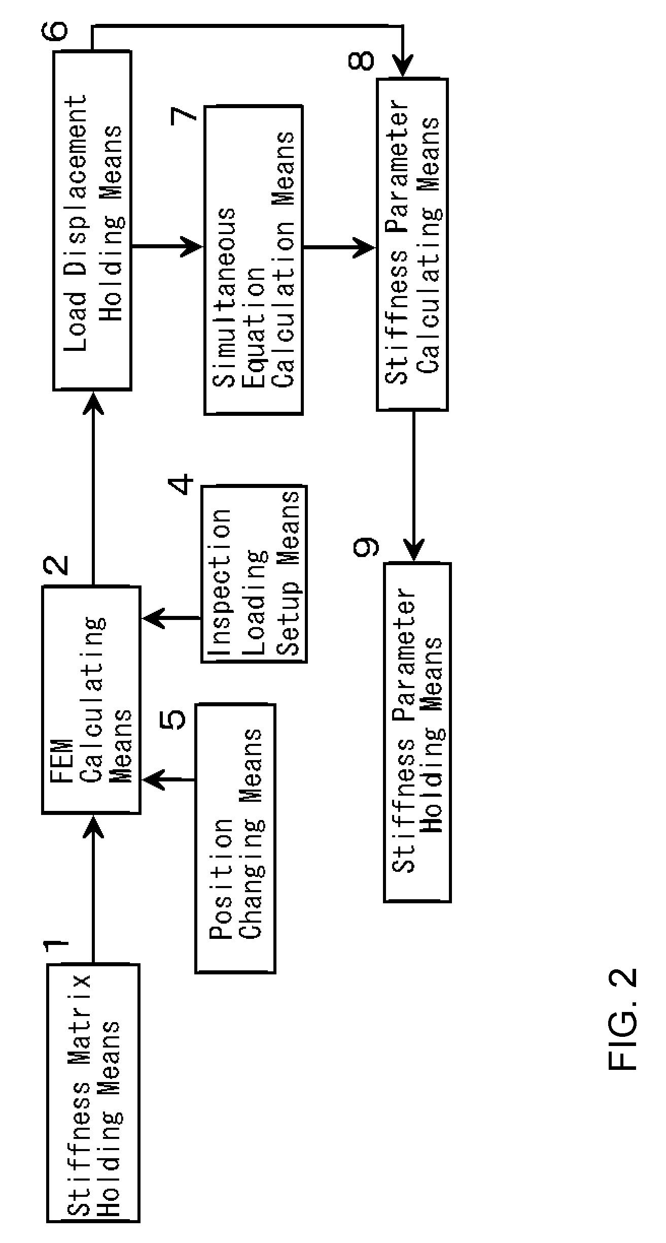
[0049]The first embodiment of this invention is the numerical structural analysis system constructed as follows. The specific loading point A and the supporting point B in the objective structure are fixed. Three independent inspection loadings are applied on the variable loading point C. Three displacements are obtained by the calculation of the loading value and the displacement of the variable loading point C with FEM. The multidimensional simultaneous linear equation with unknowns less than or equal to nine depending upon the internal stiffness matrix, the displacement of the variable loading point C and the load value of the specific loading point A is solved to obtain the partial stiffness matrix KAC. U*(C) is obtained with respect to all the necessary point C with changing the variable loading point C.
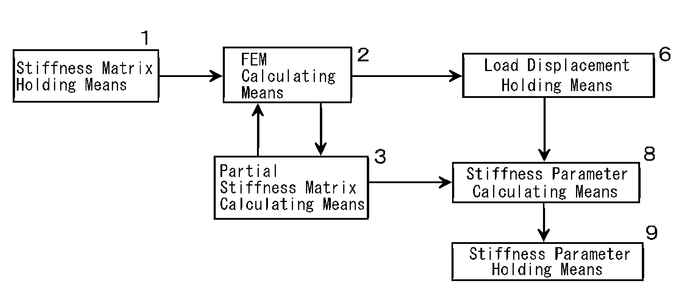
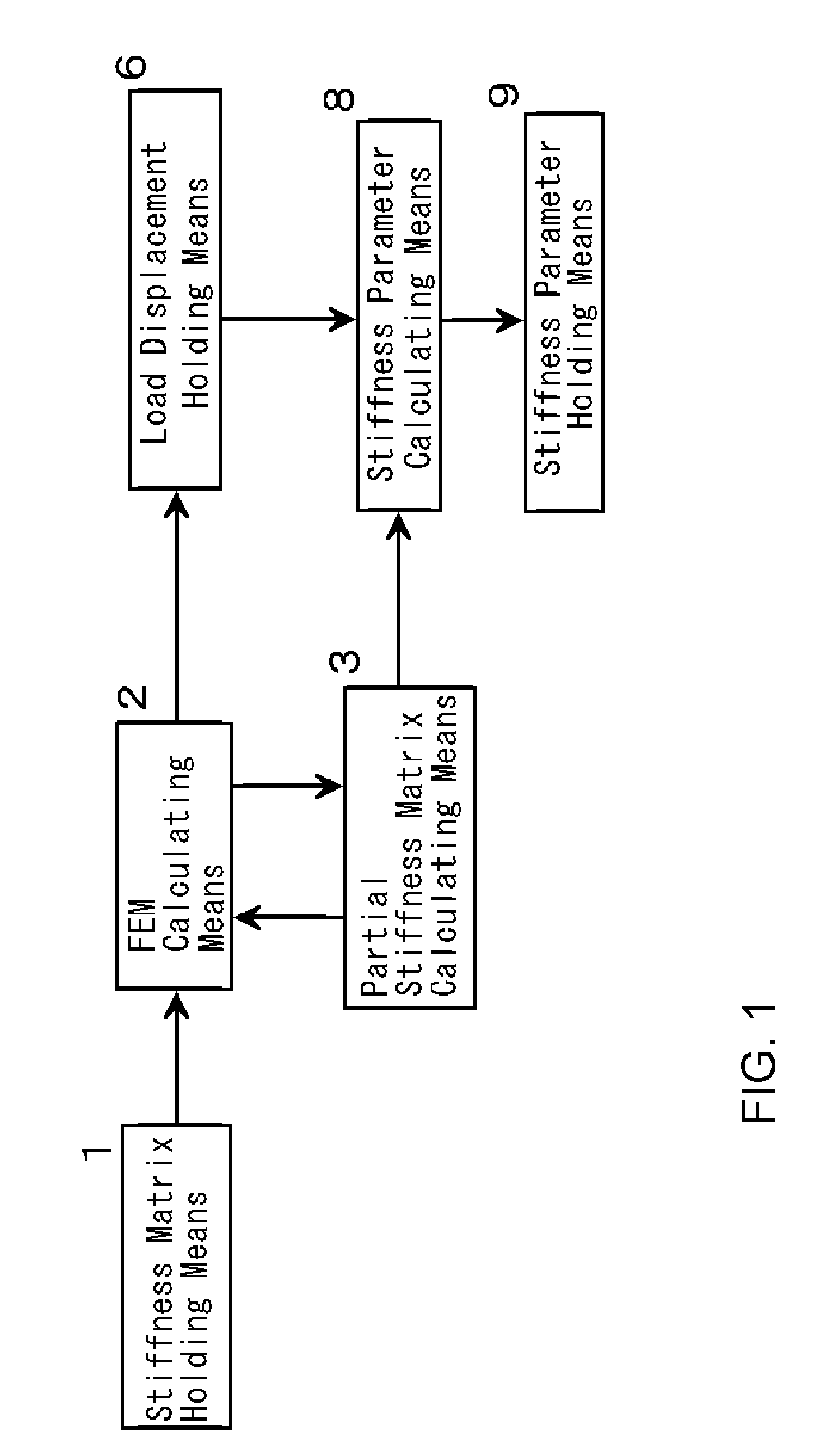
[0050]FIG. 1 shows the concept of the numerical structural analysis system of this invention. This is the numerical structural analysis system to analyze the objective structure...
embodiment 2
[0070]The second embodiment of this invention is the numerical structural analysis system constructed as follows. The reverse matrix of the structural stiffness matrix except the elements with respect to the supporting point B is calculated. The reverse matrix of the submatrix extracted the elements with respect to the specific loading point A and the variable loading point C from the former reverse matrix. The elements corresponding to the partial stiffness matrix KAC are extracted from the latter reverse matrix. U*(C) is calculated with respect to all the necessary variable loading points with changing the variable loading point C.
[0071]FIG. 6 shows the structural concept of the numerical structure analysis system of the second embodiment of this invention. In FIG. 6, the stiffness matrix holding means 1 is the means to hold the structural stiffness matrix of the objective structure. The FEM calculation means 2 is the means to calculate the deformation depending on the structural ...
PUM
 Abstract
Description
Claims
Application Information