Check patentability & draft patents in minutes with Patsnap Eureka AI!

Computer and method for reflecting path redundancy configuration of first computer system in second computer system

Inactive Publication Date: 2009-05-14
HITACHI LTD
View PDF8 Cites 14 Cited by
  • Summary
  • Abstract
  • Description
  • Claims
  • Application Information

AI Technical Summary

Benefits of technology

[0009]Therefore, an object of the present invention is to reflect the path redundancy configured in the first computer system in the second computer system without placing much of a burden on the individuals involved.

Problems solved by technology

However, configuring path redundancy manually is extremely burdensome.
For example, when the second computer system comprises anywhere from several tens of units to several hundreds of units of the second hosts, the total number of paths to be configured can number several thousand, and configuring, for the respective second storage volumes, the same path redundancy as the redundancy of the first path, which is connected to the first storage volume that configures a volume pair, is an enormous burden.

Method used


Image

  • Computer and method for reflecting path redundancy configuration of first computer system in second computer system
  • Computer and method for reflecting path redundancy configuration of first computer system in second computer system
  • Computer and method for reflecting path redundancy configuration of first computer system in second computer system

Examples


embodiment 2

[0141]A second embodiment of the present invention will be explained hereinbelow. The points of difference with the first embodiment will mainly be explained at this time, and explanations of the points shared in common with the first embodiment will be simplified or omitted.

[0142]In the first embodiment, copy-target redundancy information is sent to the integrated management computer 113 from the copy-source host 105S, and is sent from the integrated management computer 113 to the copy-target host 105T. In the second embodiment, the route via which the copy-target redundancy information is sent to the copy-target host 105T differs. More specifically, the storage volume is utilized.

[0143]FIG. 14 shows the flow of the copy-target redundancy information until it reaches the copy-target host 105T in a second embodiment of the present invention.

[0144]As shown by arrow 501, the integrated management computer 113 (integrated management software 403) writes the copy-target redundancy infor...

embodiment 3

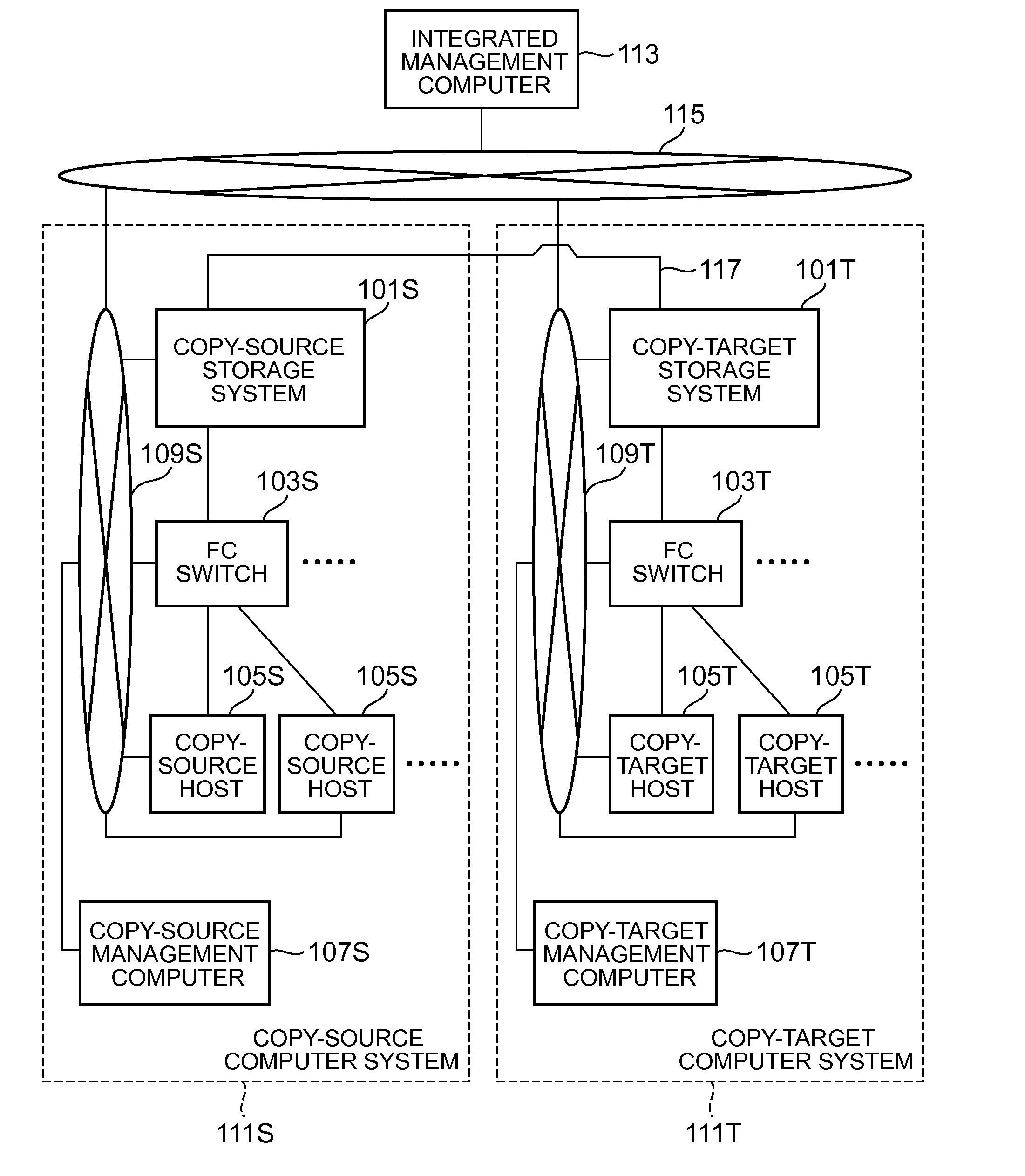
[0150]FIG. 15 shows an example of the overall constitution of a system related to a third embodiment of the present invention.

[0151]There are a plurality of copy-source computer systems 111S for one copy-target computer system 111T. In this case, for example, the copy-target computer system 111T is logically divided into a plurality of copy-target computer sub-systems as shown by the dotted line. One copy-target computer sub-system is mapped to one copy-source computer system 111S. The respective copy-target computer sub-systems have at least one copy-target host volume and at least one copy-target storage volume.

[0152]The above-described embodiments of the present invention are example for explaining the present invention, and do not purport to limit the scope of the present invention solely to these embodiments. The present invention can be put into practice in a variety of other modes without departing from the gist thereof.

[0153]For example, the processing flow disclosed in at l...


PUM


Abstract

Mapping management information denoting the mapping of a first host and first host volume and a second host and second host volume is prepared beforehand. First-path-redundancy information, which is related to the redundancy of a first path of the first host volume, is acquired, and a second host volume and second host mapped to this first host volume and the first host thereof are specified by referencing the mapping management information. The redundancy of a second path, which links the specified second host volume and a second storage volume, is decided based on the first-path-redundancy information. Second-path-redundancy information, which is related to the decided second-path redundancy, is outputted to configure the decided second-path redundancy in the above-mentioned specified second host.

Description

CROSS-REFERENCE TO PRIOR APPLICATION[0001]This application relates to and claims the benefit of priority from Japanese Patent Application number 2007-294925, filed on Nov. 13, 2007, the entire disclosure of which is incorporated herein by reference.BACKGROUND[0002]The present invention generally relates to the management of information related to a computer system constituting one or more hosts and storage systems.[0003]The so-called remote copy technique by which data stored in a first storage system is copied to a second storage system is known (Japanese Patent Laid-open No. 2006-301891, hereinafter referred to as Patent Document 1). For example, even if a disaster or the like makes it impossible to acquire data from the first storage system, a job can be continued by using the data stored in the second storage system.[0004]A first computer system can be constructed using the first storage system, and one or more first hosts connected thereto. The first host has a first host volum...

Claims


Application Information

Patent Timeline
IPC IPC(8): G06F12/00
CPCG06F3/0605G06F3/0617G06F3/0635G06F11/2097G06F11/2007G06F11/2025G06F11/2038G06F3/067
Inventor TAKEUCHI, SHINYA
Owner HITACHI LTD
Features
  • R&D
  • Intellectual Property
  • Life Sciences
  • Materials
  • Tech Scout
  • Unparalleled Data Quality
  • Higher Quality Content
  • 60% Fewer Hallucinations
Learn More