
Refueling boom with backup raising cable

a technology of raising cable and refueling boom, which is applied in the direction of aircraft components, transportation and packaging, etc., can solve the problems of possible destruction of the boom and other collateral effects

Inactive Publication Date: 2009-05-21
EADS CONSTRS AERONAUTICAS
View PDF6 Cites 10 Cited by
  • Summary
  • Abstract
  • Description
  • Claims
  • Application Information

AI Technical Summary

Benefits of technology

[0007]The cable actuator has rolling means to roll the cable for raising the boom to the stowed position. When not in use, this secondary cable does not interfere in the normal refueling operation and it remains fixed to the tanker.

Problems solved by technology

Should this cable breaks, this will conduct to a problematic landing operation with the possible destruction of the boom and possibly other collateral effects.

Method used


Image

  • Refueling boom with backup raising cable
  • Refueling boom with backup raising cable

Examples


Embodiment Construction

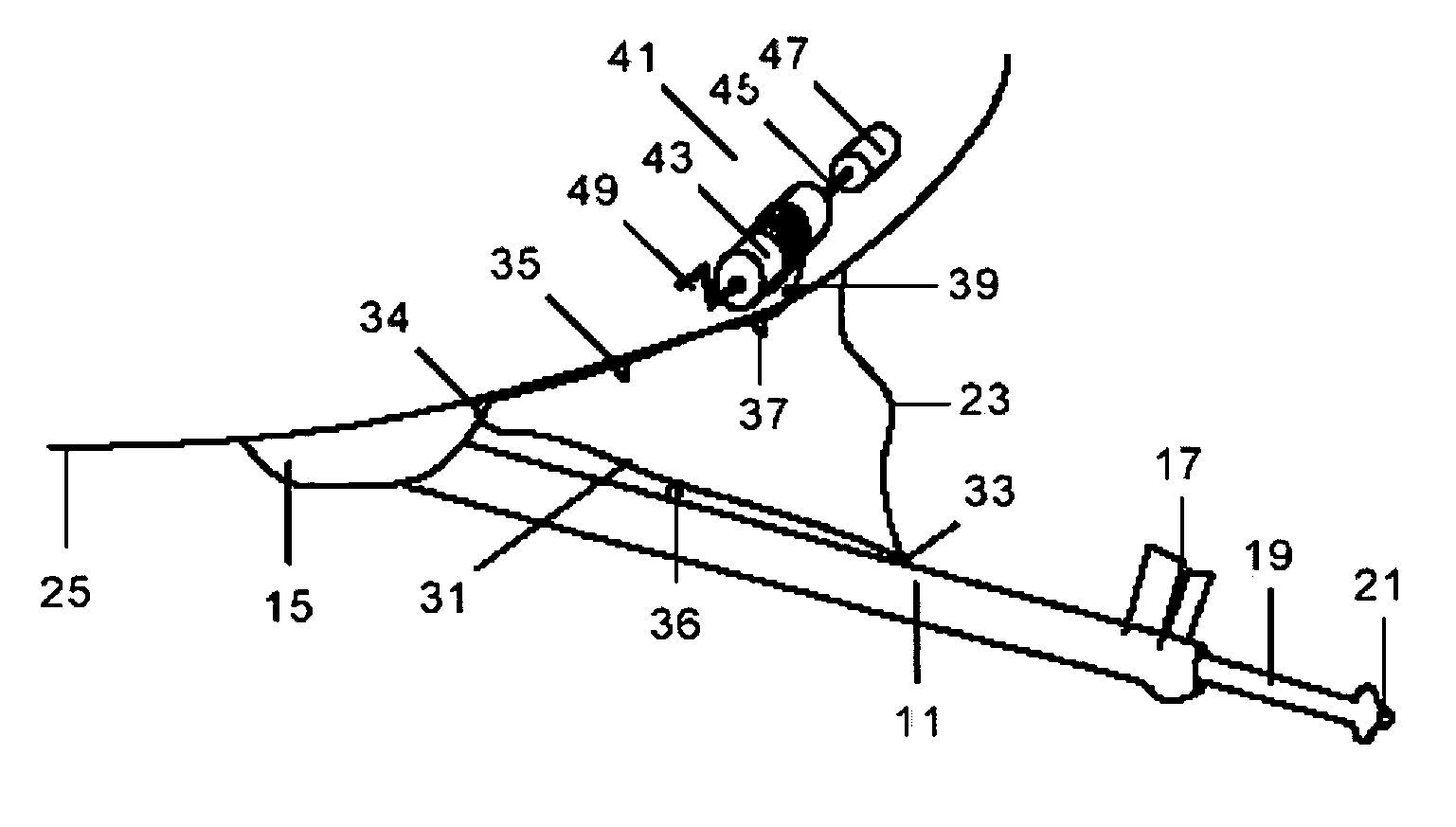
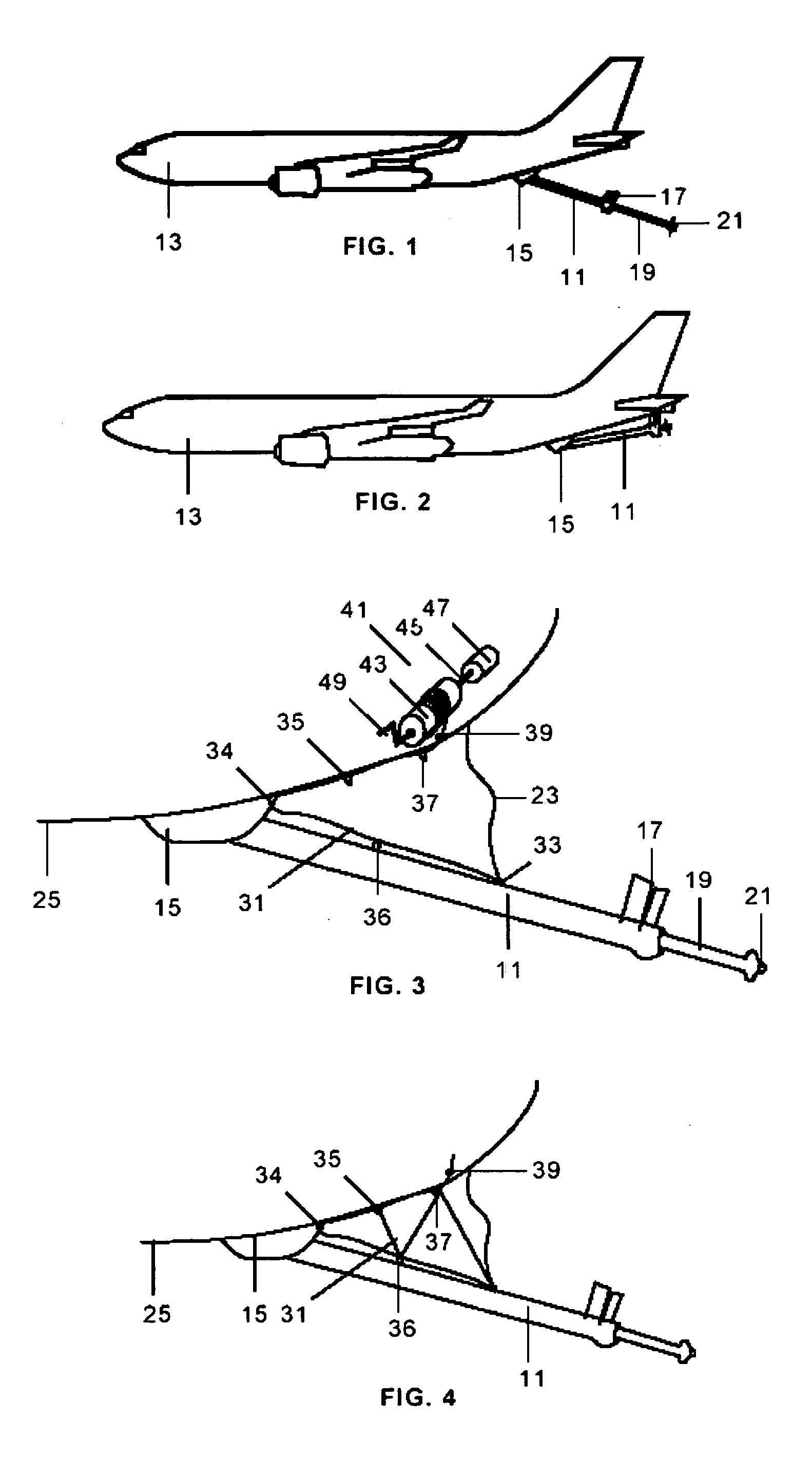
[0013]An aircraft refueling boom 11 is a telescoping beam fuel-tight unit with its forward end attached to the underside 25 of a tanker aircraft 13 by means of a mechanical articulation 15. Integrally attached to the boom 11 are ruddevators 17 which are used to aerodynamically control the position of the boom 11 in elevation and azimuth.

[0014]The outer end portion 19 of the boom 11 is a telescoping section for inward and outward movement. Located on the distal end of the telescoping tube 19 is a nozzle 21. The receiver aircraft, not shown, is equipped with an aerial refueling receptacle which engages with the nozzle 27 for the refueling operation.

[0015]The boom 11 is attached to the tanker aircraft by means of a hoist cable 23 that must follow the movements of the boom 11 to avoid any disturbance to its flying properties.

[0016]The secondary cable 31 is fixed in one side to the boom 11 in a point 33, preferably located in its central part and in the other side to the cable actuator 4...


PUM


Abstract

The invention relates to a backup device for raising a refueling boom (11) interconnecting a tanker aircraft (13) with a receiver aircraft in flight, said boom (11) being joined to said tanker aircraft (13) by means of a mechanical articulation (45) and a hoist cable (23), comprising a secondary cable (31) fixed at one side in the boom (11), fixed at the other side in a cable actuator (41) placed inside the tanker aircraft (13), said secondary cable (31) being extended along the underside (25) of the tanker aircraft (13) and along the boom (11), and attached to them in at least three intermediate points with means (34, 35, 36, 37) that can be released by a force exerted through the secondary cable (31), said cable actuator (41) having rolling means (43, 45, 47, 49) to roll the secondary cable (31) for raising the boom (11) to the stowed position.

Description

TECHNICAL FIELD[0001]The present invention relates generally to aircraft refueling booms and more specifically to an aircraft refueling boom system having backup raising cable.BACKGROUND[0002]For in flight refueling operations, one usual method is based on the use of a boom device for interconnecting a tanker aircraft with a receiver aircraft in flight, which is basically a telescopic tube which is attached to the underside of the tanker aircraft by means of an articulation element. The boom moves around this fixed point during the refueling operation using a pair of aerodynamic lift surfaces known as ruddevators.[0003]The boom is also attached to the tanker aircraft by means of a hoist cable to raise the boom to its stowed position to permit landing and other non refueling operations. When the boom is in operation this cable is dynamically coiled to suitable means to always follow the distance between the boom and the aircraft to maintain tension without interfering with the boom m...

Claims


Application Information

Patent Timeline
Patent Type & Authority Applications(United States)
IPC IPC(8): B64D39/00
CPCB64D39/00
Inventor ADARVE LOZANO, ALBERTO
Owner EADS CONSTRS AERONAUTICAS
Features
  • Generate Ideas
  • Intellectual Property
  • Life Sciences
  • Materials
  • Tech Scout
  • Unparalleled Data Quality
  • Higher Quality Content
  • 60% Fewer Hallucinations
Learn More