

Ink jet recording head, ink jet cartridge, and method for manufacturing ink jet recording head
- Summary
- Abstract
- Description
- Claims
- Application Information
AI Technical Summary
Benefits of technology
Problems solved by technology
Method used
Image

Examples
embodiment 1
(General Structure of Ink Jet Recording Apparatus)
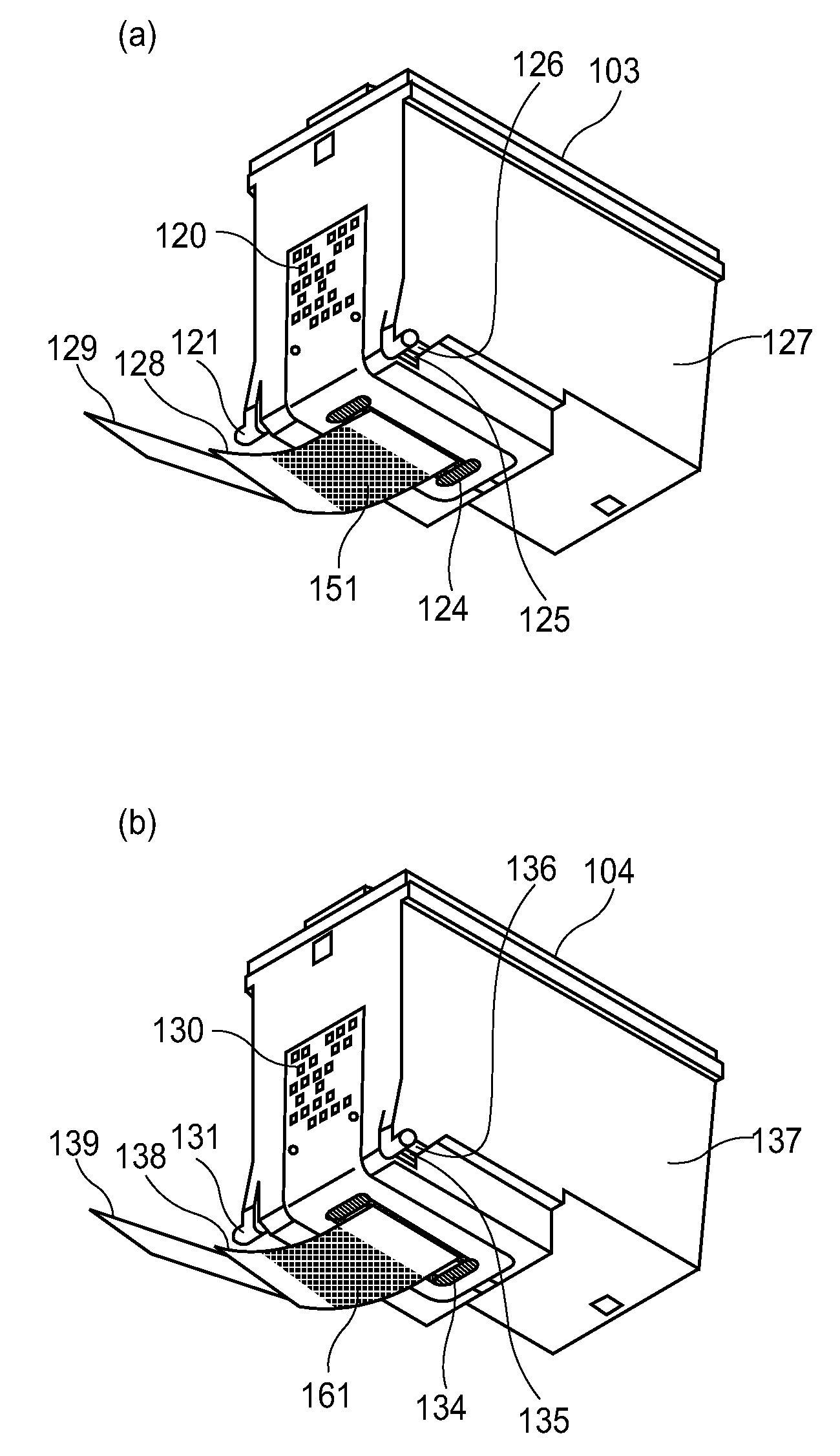
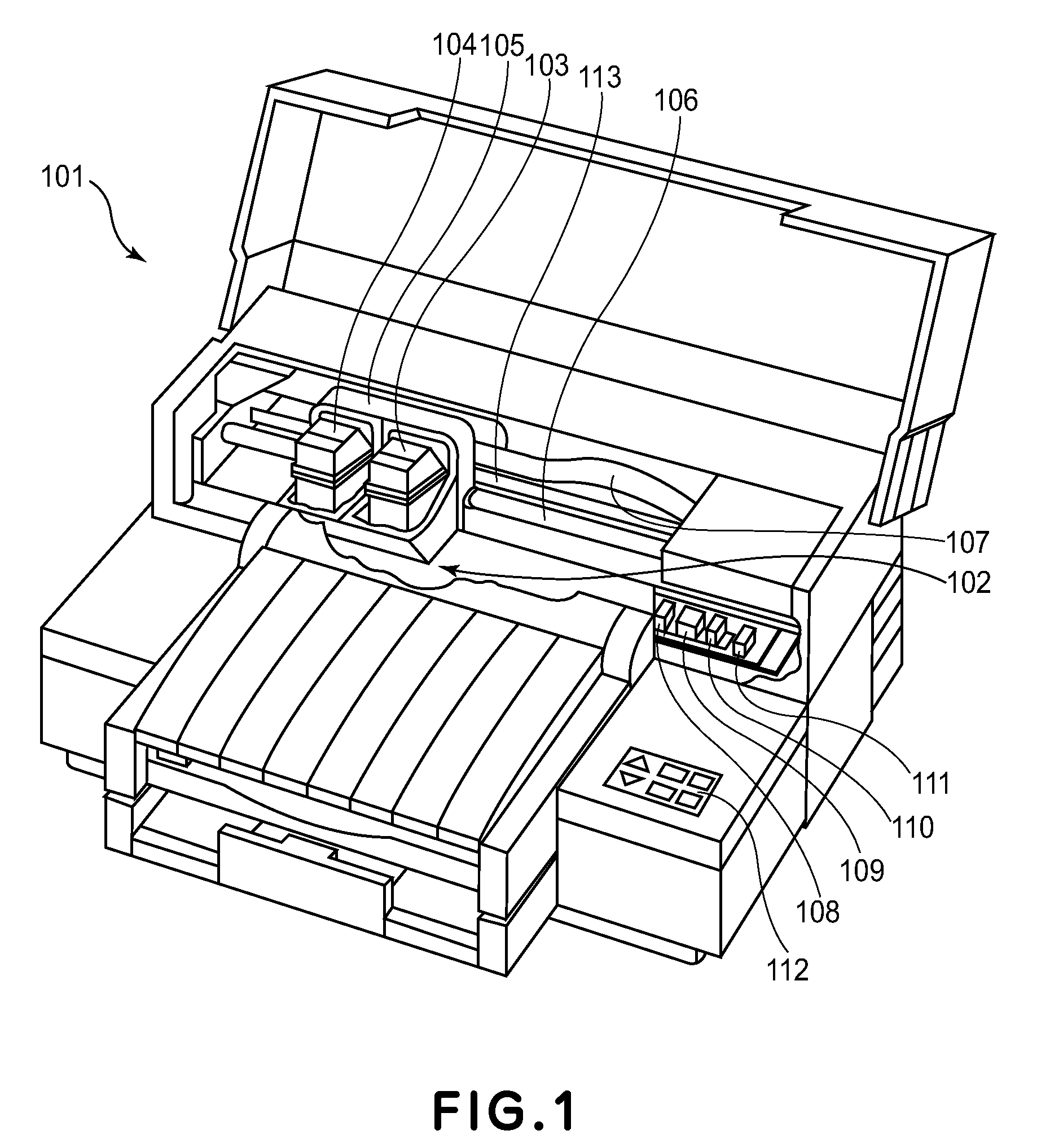
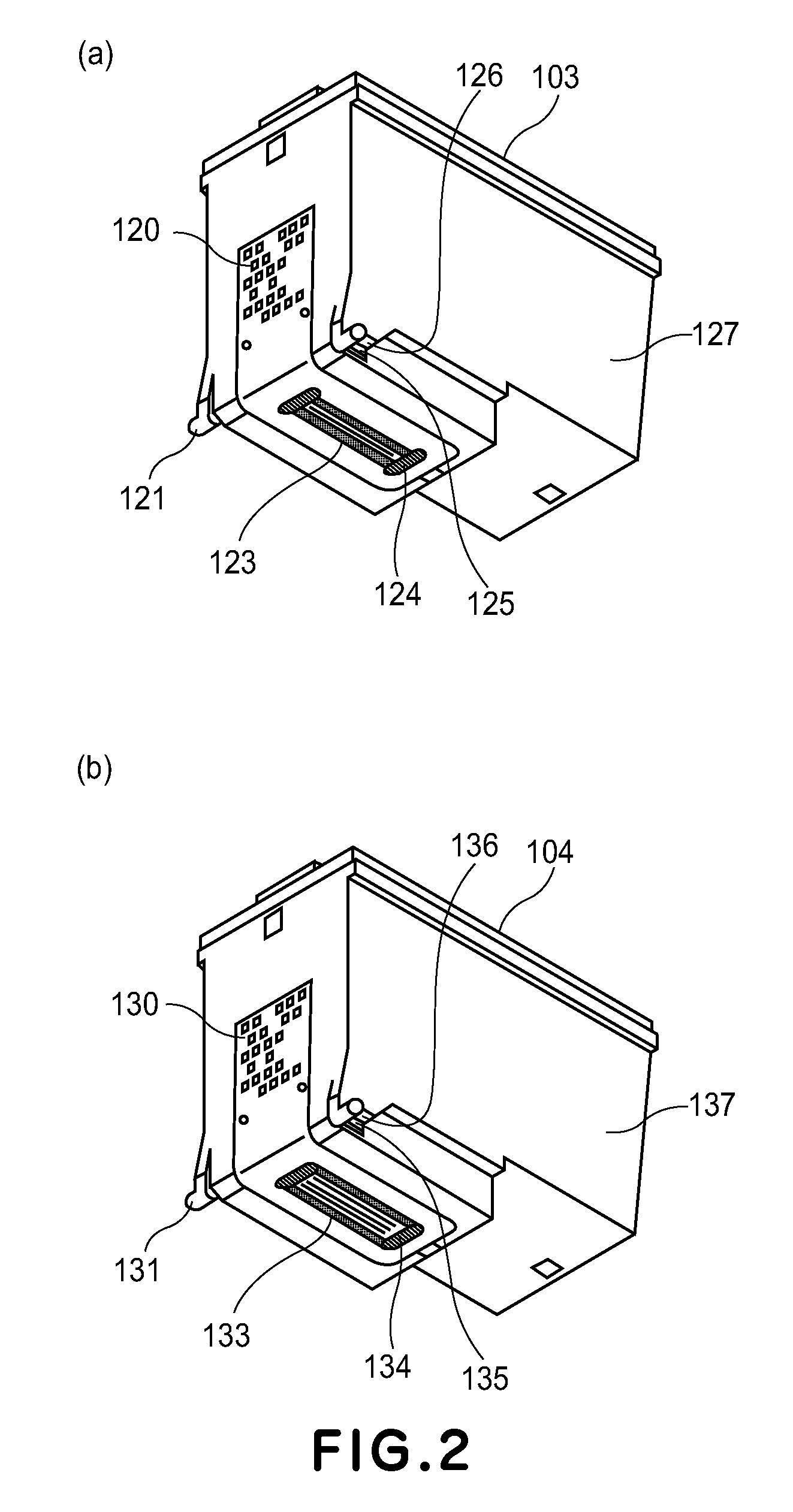
[0035]FIG. 1 is a perspective view of a typical ink jet recording apparatus, to which the ink jet recording cartridge in the first preferred embodiment of the present invention, is removably mountable. The ink jet recording apparatus 101 is provided with an ink jet recording cartridge 104 for printing in color (which hereafter may be referred to as CI cartridges), and an ink jet recording cartridge 103 for printing in black (Bk) (which hereafter may be referred to as Bk cartridge). The Cl cartridge is provided with three parallel rows of nozzles for jetting cyan (C), magenta (M), and yellow (Y) inks, one for one. The Bk cartridge is provided with a single row of nozzles for jetting black (Bk) ink. Both cartridges are provided with an ink jet recording head capable of jetting ink, and an ink container. The ink jet recording apparatus 101 is made up of: a carriage 105 which holds the two cartridges 104 and 103; a guide shaft 106 for gu...
embodiment 2
[0058]FIG. 10 is a plan view of the ink jet recording cartridge in the second embodiment of the present invention. This ink jet recording cartridge 138 is also provided with the protective tape 138 which was pasted to the recording element as it was in the first embodiment. This embodiment (including devices used for testing of ink jet recording cartridge) is the same as the first embodiment, except for the area(s) of the surface of the recording element, which is irradiated with UV light.
[0059]Designated by a referential number 13 is each of the areas of the recording element which are irradiated with UV light. The area 13 is smaller than the area 11, that is, the surface area of the recording element, which was irradiated with the UV light in the first embodiment. The areas 13 also belong to the surface of the recording element, which has the nozzle openings. Each of the areas 13 constitutes a part of the corresponding lengthwise end of the surface having the nozzle openings, as d...
embodiment 3
[0068]FIG. 12 is a schematic plan view of the ink jet recording cartridge in the third embodiment of the present invention. The ink jet recording cartridge in this embodiment is provided with the protective tape 128, which is pasted to the recording element 123, as the protective tape 128 was in the first and second embodiments. The ink jet recording cartridge in this embodiment is the Bk cartridge 103. This embodiment (including devices such as those used for testing of ink jet recording cartridge) is the same as the first and embodiments, except for the surface areas of the recording element, which are irradiated with the UV light. That is, in this embodiment, the surface of the recording element, which has the nozzle openings, is irradiated with the UV light so that only the areas of the surface, which are most suitable for achieving the objects of the present invention, are irradiated with the UV light.
[0069]Designated by a referential number 21 is the surface area of the record...
PUM
 Abstract
Description
Claims
Application Information