Support foot apparatus and methods
- Summary
- Abstract
- Description
- Claims
- Application Information
AI Technical Summary
Benefits of technology
Problems solved by technology
Method used
Image
Examples
Embodiment Construction
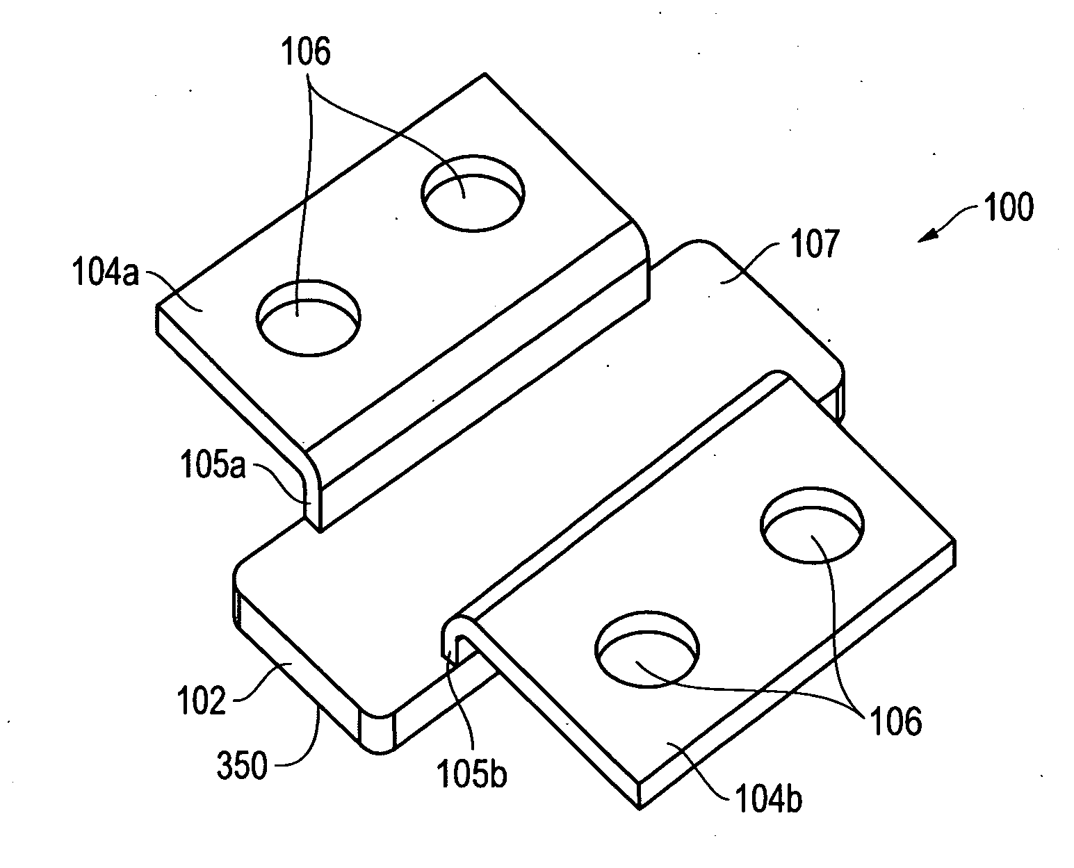
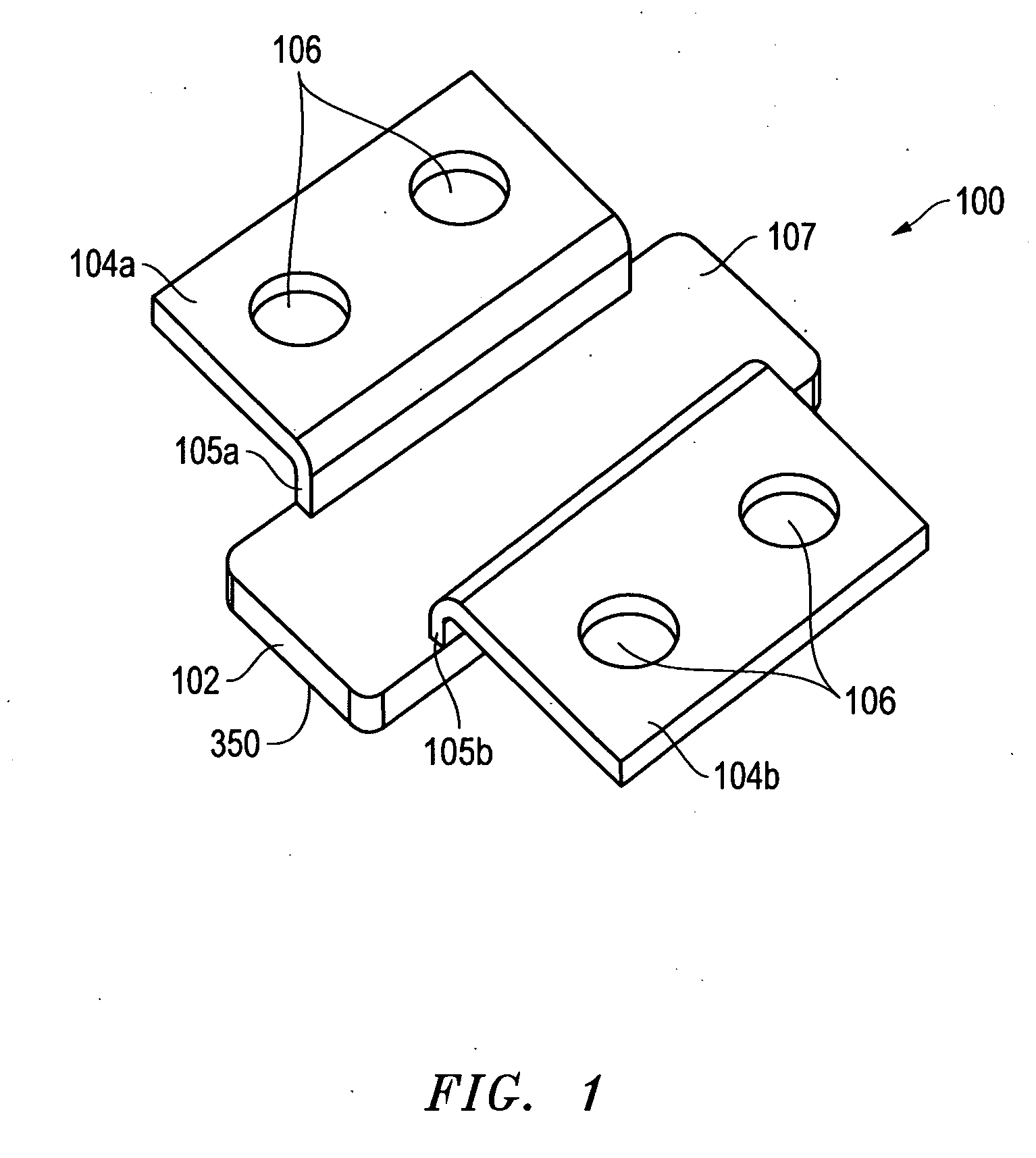
FIG. 1 illustrates a perspective view of one exemplary embodiment of a resilient support foot apparatus 100 that includes a central foot member 102 with two opposing flexible flap members 104a and 104b that in this embodiment each include a respective flexible offset section 105a or 105b that couples the respective flexible flap member 104a or 104b to central foot member 102. As further shown, support foot apparatus 100 includes two securing apertures 106 defined in each of flexible flap members 104a and 104b. Each of securing apertures 106 is configured for placement over a corresponding securing post provided on an interior surface of an information handling system chassis or other type of device chassis as will be described further herein. A chassis side surface 107 is provided for contact with an exterior side of a device chassis is provided on one side of central foot member 102, and a support side surface 350 is provided on the opposing side of central foot member 102 as shown...
PUM
| Property | Measurement | Unit |
|---|---|---|
| Time | aaaaa | aaaaa |
| Time | aaaaa | aaaaa |
| Flexibility | aaaaa | aaaaa |
Abstract
Description
Claims
Application Information
 - R&D
- Intellectual Property
- Life Sciences
- Materials
- Tech Scout
- Unparalleled Data Quality
- Higher Quality Content
- 60% Fewer Hallucinations
Browse by: Latest US Patents, China's latest patents, Technical Efficacy Thesaurus, Application Domain, Technology Topic, Popular Technical Reports.
© 2025 PatSnap. All rights reserved.Legal|Privacy policy|Modern Slavery Act Transparency Statement|Sitemap|About US| Contact US: help@patsnap.com


