Multiplexing apparatus in a transceiver system

a transceiver and multi-channel technology, applied in the field of multi-channel multi-channel apparatus in a transceiver system, can solve the problems of increasing the cost of installation and maintaining a cell tower, increasing the wind-load of a tower, and high cost of radio frequency cables

Active Publication Date: 2009-05-21
STRONG FORCE IOT
View PDF11 Cites 4 Cited by
  • Summary
  • Abstract
  • Description
  • Claims
  • Application Information

AI Technical Summary

Problems solved by technology

The radio frequency cables, which typically extend from the bottom to the top of the cell tower, are expensive, costly to install, and increase wind-loading on a tower.
As the number of radio frequency cables in a cell tower increases, the cost of installing and maintaining cell tower increases.

Method used


Image

  • Multiplexing apparatus in a transceiver system
  • Multiplexing apparatus in a transceiver system
  • Multiplexing apparatus in a transceiver system

Examples


Embodiment Construction

[0014]In the following detailed description, reference is made to the accompanying drawings that form a part hereof, and in which is shown by way of illustration specific illustrative embodiments in which the invention may be practiced. These embodiments are described in sufficient detail to enable those skilled in the art to practice the invention, and it is to be understood that other embodiments may be utilized and that logical, mechanical and electrical changes may be made without departing from the scope of the present invention. The following detailed description is, therefore, not to be taken in a limiting sense.

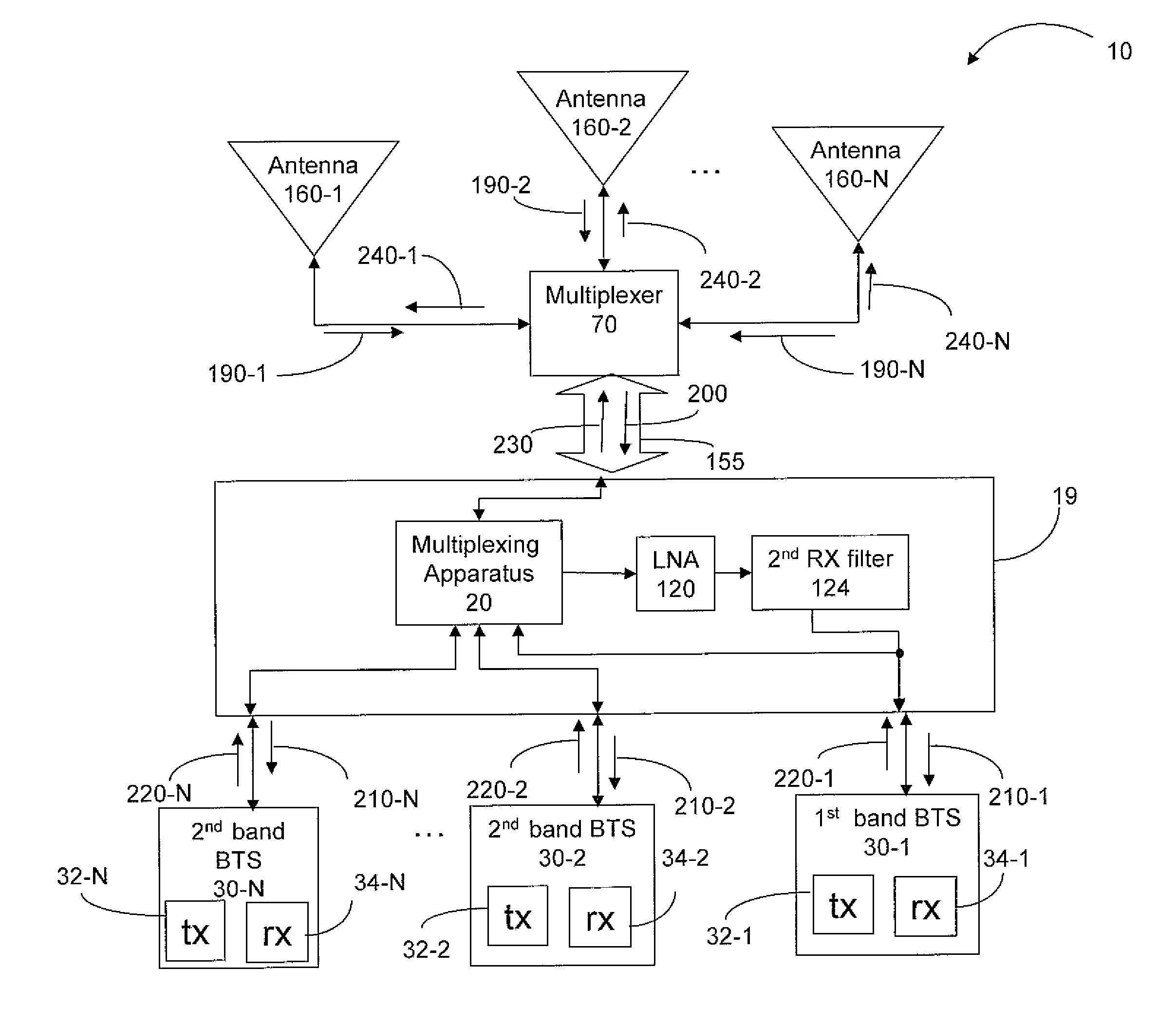
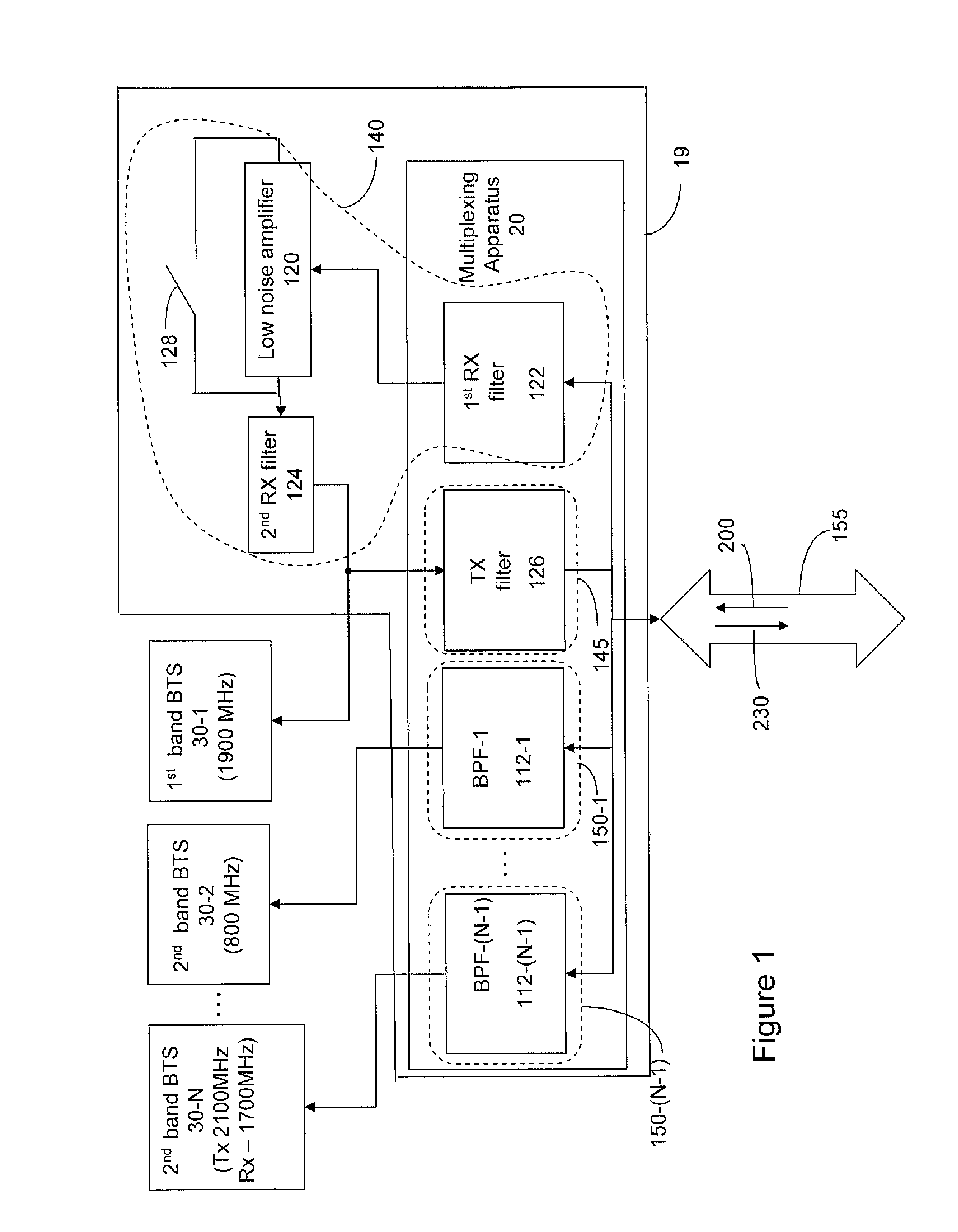
[0015]FIG. 1 is a block diagram of one embodiment of a multiplexing apparatus 20 in accordance with the present invention. The multiplexing apparatus 20 includes at least one band pass filter 112(1-(N-1)), a receiver filter 122, and a transmitter filter 126. The multiplexing apparatus 20 is communicatively coupled with a plurality of base transceiver stations 30(1-N)....


PUM


Abstract

A multiplexing apparatus comprising at least one band pass filter, a receiver filter, and a transmitter filter is disclosed. The receiver filter, the transmitter filter and each band pass filter are communicatively coupled to a cable so that the receiver filter is configured to pass signals in a first spectral region from the cable to a first-band base transceiver station, the transmitter filter is configured to pass signals in the first spectral region from the first-band base transceiver station to the cable, and each band pass filter is configured to filter and bi-directionally pass signals in a second spectral region between the cable and at least one other base transceiver station.

Description

BACKGROUND[0001]It is desirable for telecom carriers to minimize the number of radio frequency cables used to communicatively couple base stations to the antennae located atop a cell tower. The radio frequency cables, which typically extend from the bottom to the top of the cell tower, are expensive, costly to install, and increase wind-loading on a tower. As the number of radio frequency cables in a cell tower increases, the cost of installing and maintaining cell tower increases.[0002]FIG. 2 is a block diagram of a prior art embodiment of a multiplexer 29. As shown in FIG. 2, the current technology to reduce the number of radio frequency cables to one cable 155 used to communicatively couple base stations 28(1-N) to the antennae (not shown) located atop a cell tower (not shown) comprises band pass filters 111(1-N).SUMMARY[0003]Disclosed is a multiplexing apparatus comprising at least one band pass filter, a receiver filter, and a transmitter filter. The receiver filter, the transm...

Claims


Application Information

Patent Timeline
Patent Type & Authority Applications(United States)
IPC IPC(8): H04J15/00H04L5/00
CPCH04L5/08
Inventor HEUER, WILLIAM C.KASAHARA, YOSHI
Owner STRONG FORCE IOT
Why Eureka
Try Eureka