
Hearing aid method for in-situ occlusion effect and directly transmitted sound measurement

a technology of in-situ occlusion and hearing aids, applied in the field of hearing aids, can solve the problems of inability to drill a larger vent, user may perceive his or her own voice as hollow or booming, and the effect of occlusion is well-known

Active Publication Date: 2009-05-21
WIDEX AS
View PDF2 Cites 46 Cited by
  • Summary
  • Abstract
  • Description
  • Claims
  • Application Information

AI Technical Summary

Benefits of technology

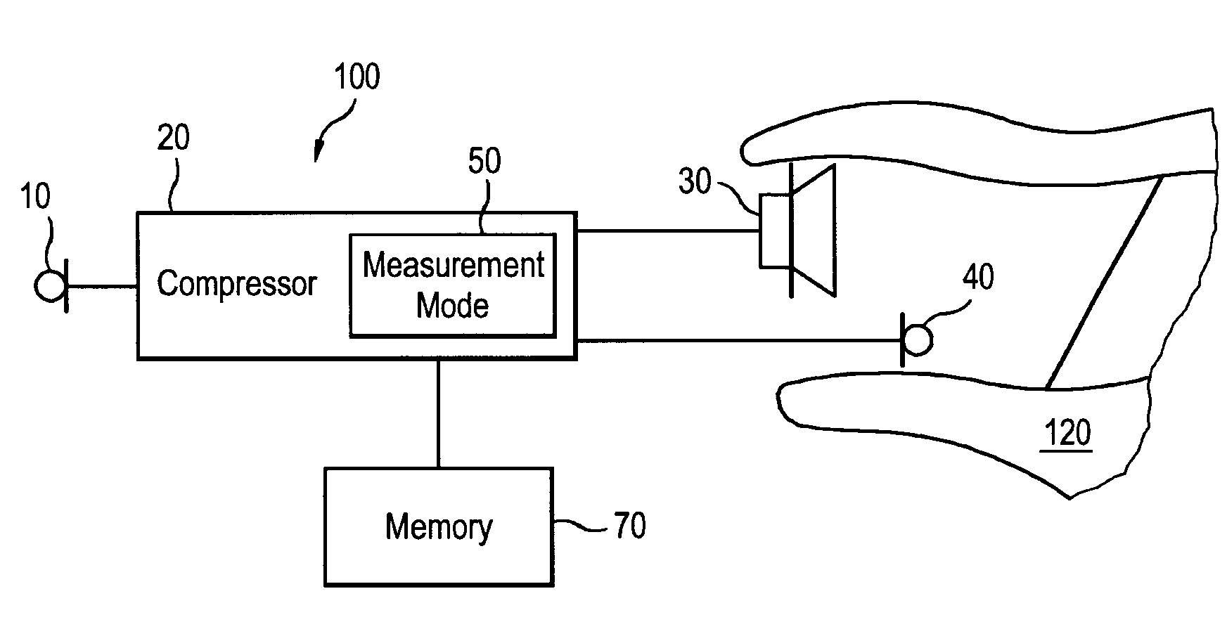
[0017]Such an embodiment has the advantage that in case of a person fitted binaurally, one hearing aid could be used to measure the sound in the occluded ear by means of, for example, a probe tube, while the opposite hearing aid could be relied on for measuring the ambient sound level.
[0023]It is therefore another feature of the present invention to provide hearing aids and methods which are capable of distinguishing between sounds in front of the ear drum resulting from occlusion effect from sounds in front of the ear drum resulting from directly transmitted sound.
[0026]It is another feature of the present invention to provide methods, which allow fitting of a prospective hearing aid taking into account the occlusion effect.
[0028]It is another feature of the present invention to provide methods, which allow automatic vent size counseling regarding a hearing aid based on in-situ occlusion effect measurement.

Problems solved by technology

The occlusion effect is a well-known problem for hearing aid users.
A user may thus perceive his or her own voice as hollow or booming, which in particular is annoying if the hearing loss is small in the low frequencies.
However, in particular for CIC and ITE hearing aids, drilling a larger vent is not possible, and would therefore demand the production of an entirely new hearing aid.
By the current practice it is therefore not possible to predict the occlusion effect very well.
Directly transmitted sound may interfere with signals output by the hearing aid causing a decrease of the speech intelligibility and overall sound quality for the user.

Method used


Image

  • Hearing aid method for in-situ occlusion effect and directly transmitted sound measurement
  • Hearing aid method for in-situ occlusion effect and directly transmitted sound measurement
  • Hearing aid method for in-situ occlusion effect and directly transmitted sound measurement

Examples


Embodiment Construction

[0048]When describing the invention according to embodiments thereof, terms will be used which are described as follows.

[0049]The occlusion effect (OE) is defined as the difference between the sound levels just in front of the ear drum in the occluded versus the un-occluded ear while the user speaks or vocalizes sound and when the hearing aid is not active.

[0050]The sound uttered by a user is generated in the throat (glottis) as harmonics of a fundamental frequency, and is shaped by the area function of the vocal tract. The sound generated spreads as air conducted sound as well as bone conducted sound, the latter in form of vibrations in the skull. In the ear canal, mainly the cartilaginous part of the ear canal radiates sound into the ear canal. This sound mainly propagates out of the open ear, but in case the ear is occluded, mainly the low frequency part of this sound propagates to the eardrum instead. This increases the low frequency sound pressure at the eardrum in the occluded...


PUM


Abstract

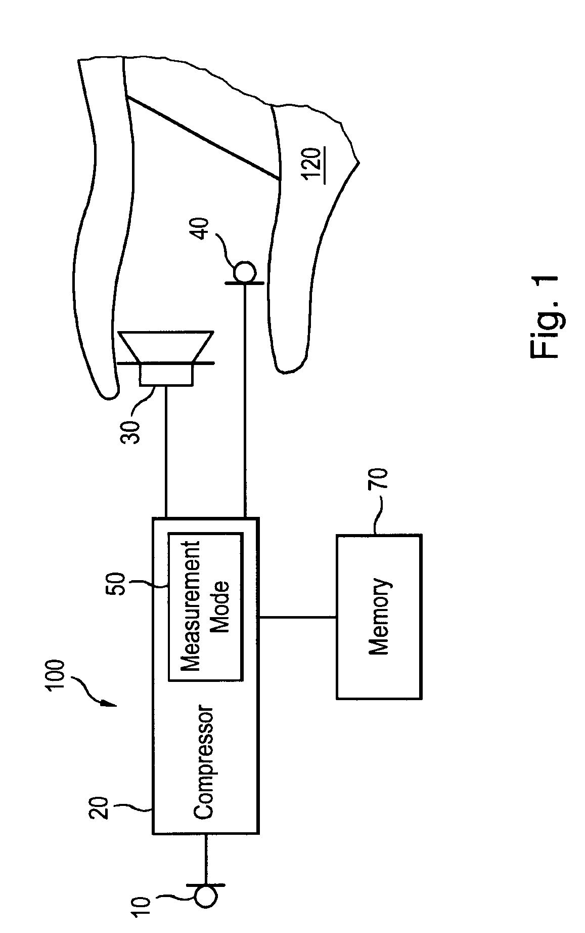
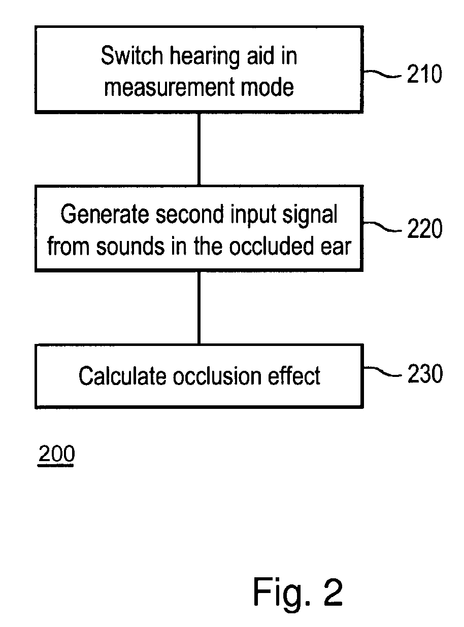
A hearing aid (100) comprises at least one first microphone (10) generating a first input signal from sounds external to a user of the hearing aid, signal processing means, a receiver (30) and, a second microphone (40) generating a second input signal from sounds in the occluded ear of the user. In a measurement mode the signal processing means produces an occlusion effect value or directly transmitted sound value from the difference between the sound levels of the second and the first input signals generated both at the same time while the receiver is silent. The invention further provides a system and a method for determining an occlusion effect and a directly transmitted sound value.

Description

RELATED APPLICATIONS[0001]The present application is a continuation-in-part of application no. PCT / EP2006 / 065125 filed on Aug. 7, 2006 and published as WO-A1-2008017326, the contents of which are incorporated herein by reference.BACKGROUND OF THE INVENTION[0002]1. Field of the Invention[0003]The present invention relates to the field of hearing aids. The invention, more specifically relates to hearing aids and methods utilizing in-situ occlusion effect or in-situ directly transmitted sound measurement. In addition, the invention relates to a method for vent size determination, a method for fitting a hearing aid based on measured in-situ occlusion effect, and a hearing aid with a customized ear plug.[0004]2. Description of the Related Art[0005]The occlusion effect is a well-known problem for hearing aid users. When someone speaks, sound is likely to propagate through bone conduction to the inside of the ear canal. The sound pressure level at the ear drum due to the person speaking is...

Claims


Application Information

Patent Timeline
IPC IPC(8): H04R25/00
CPCH04R2460/11H04R25/70
Inventor NORDAHN, MORTEN AGERBAK
Owner WIDEX AS
Learn More