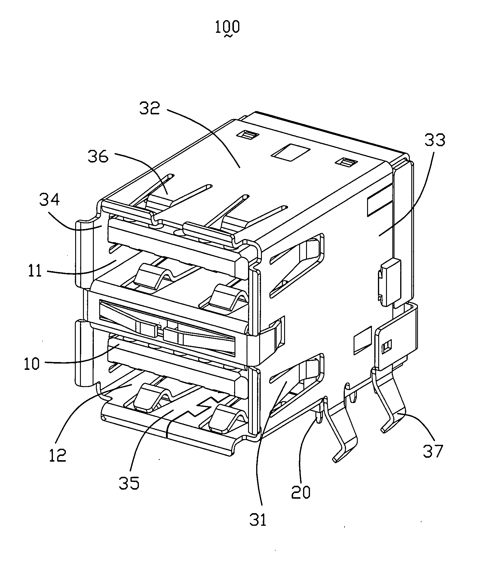
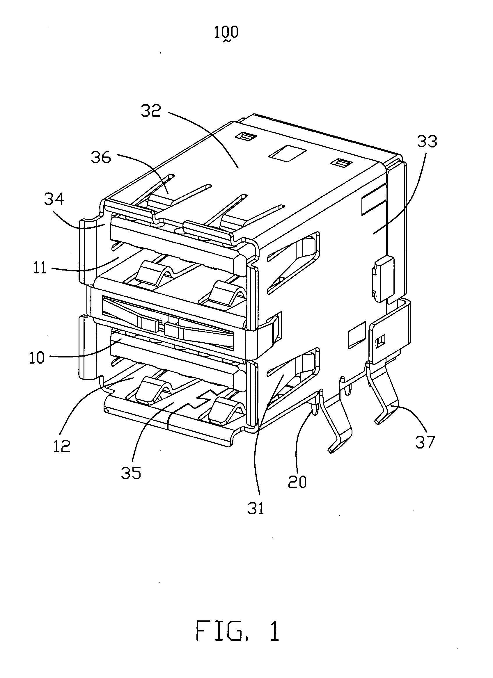
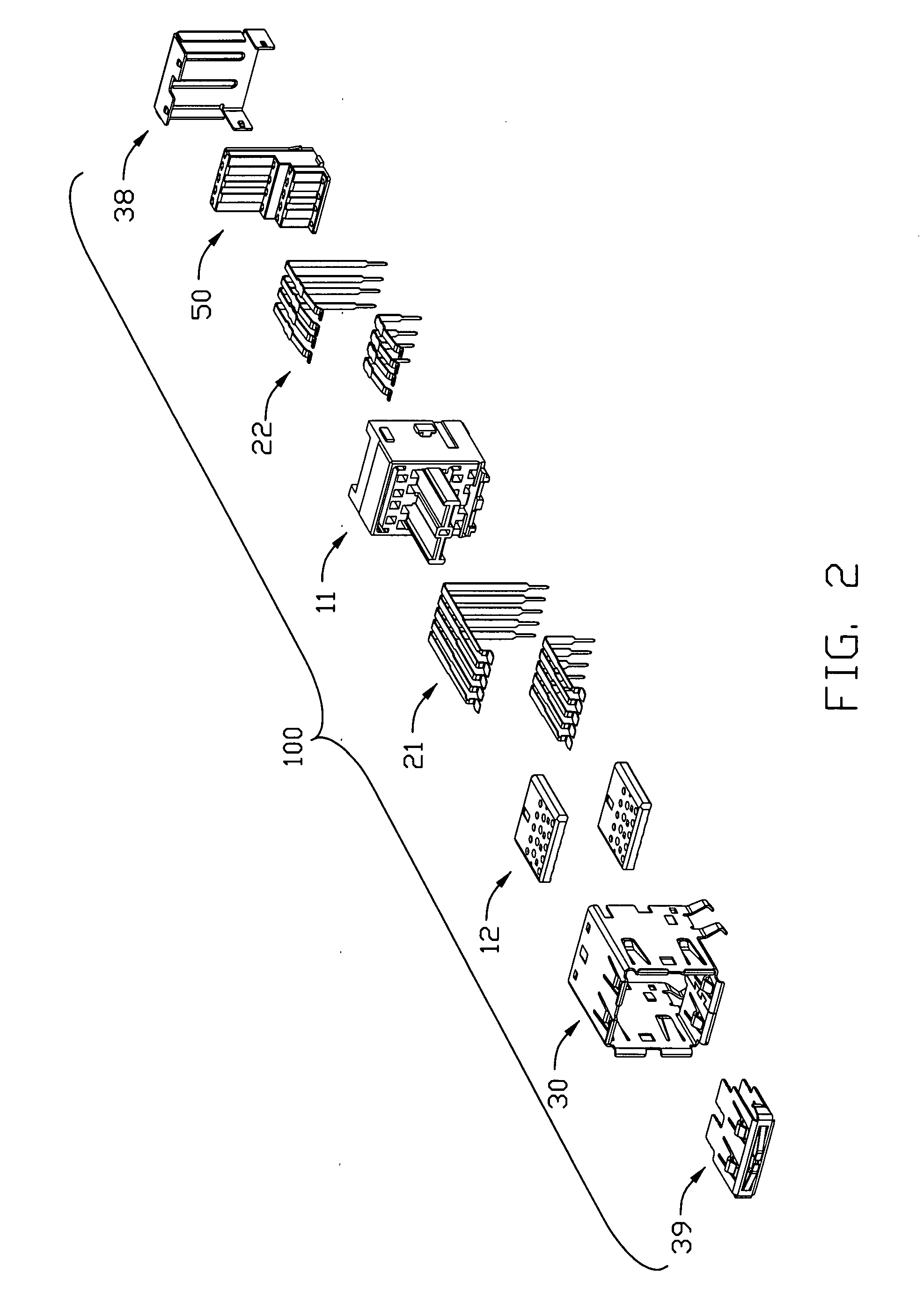
Electrical connector with ESD protection

a technology of electrical connectors and protection devices, applied in the direction of coupling devices, testing/measuring connectors, coupling devices, etc., can solve the problems of esd problems, high voltage can be high enough to damage or destroy certain types of electrical devices such as semiconductor devices, electrostatic discharge can damage or destroy electrical devices on circuit boards, etc., to achieve the effect of improving electrical contacts

Active Publication Date: 2009-05-21
HON HAI PRECISION IND CO LTD
View PDF4 Cites 36 Cited by
  • Summary
  • Abstract
  • Description
  • Claims
  • Application Information

AI Technical Summary

Problems solved by technology

Generally, very little current is associated with an electrostatic discharge; however, the voltage can be high enough to damage or destroy certain types of electrical devices such as semiconductor devices.
Consequently, when the connector contacts or terminals are electrically associated with such devices on a circuit board, the electrostatic discharge may damage or destroy the electrical devices on the circuit board.
At the front area of the electrical connector 300, there is a potential for the high speed contacts 60 to short with the shell 80 of the mating plug 200 which could also result in ESD problem.

Method used


Image

  • Electrical connector with ESD protection
  • Electrical connector with ESD protection
  • Electrical connector with ESD protection

Examples


second embodiment

[0038]Next referring to FIGS. 9 to 11, description will be made of a connector 100′ according to the present invention. The connector 100′ comprises a plurality of electrical contacts 20′, an insulative housing holding the electrical contacts 20′ thereon, and a shield (not shown) surrounding all of the above mentioned components. The insulative housing comprises a base portion 13′, two wafers 14′, 15′, and a latch mechanism for fastening the wafers 14′, 15′ to the base portion 13′. The electrical contact 20′ also includes a set of upper contacts 21′ and a set of lower contacts 22′.

[0039]The electrical connector 100′ is similar to the electrical connector 100 except the wafer 14′, 15′ and the base portion 13′. The base portion 13′ comprises a rectangular body 130′ provided with two receiving spaces 131′ therein and a plurality of passageways 134′ below the receiving spaces 131′. Each wafer 14′, 15′ comprises a tongue 140′ and a retention portion 141′ extending into the receiving spac...

third embodiment

[0041]As illustrated in FIGS. 12 to 15, description will be made of a connector 100″ according to the present invention. The connector 100″ comprises a plurality of electrical contacts 20″, an insulative housing 10″ holding the electrical contacts 20″ thereon, and a shield (not shown) surrounding all of the above mentioned components. The insulative housing 10″ comprises a base portion 13″, two wafers 14″, 15″, and a latch mechanism for fastening the wafers 14″, 15″ to the base portion 13″.

[0042]The electrical contact 20″ also includes a set of upper contacts 21″ and a set of lower contacts 22″. Each upper contact 21″ comprises a contact section 214″ exposed to a receiving space for receiving the plug 200 and a mounting section 213″ extending out of the base portion 13″. Each lower electrical contact 22″ comprises an elastic contact section 223∝ extending into the receiving space and a mounting section 224″ extending out of the base portion 13″.

[0043]The base portion 13″ comprises a...


PUM


Abstract

An electrical connector (100) for receiving a mating plug (200) having an insulative housing (10), a set of first contacts (21), and a set of second contacts (22). The insulative housing includes a base portion (13), a wafer (14), and a latch mechanism fastened the wafer to the base portion. The electrical contacts are attached to the insulative housing and each has a contact section (214, 222) connecting with the plug and a mounting section (213, 224) extending out of the insulative housing. The contact sections of the first contacts are staggered with the contact sections of the second contacts along a mating direction of the electrical connector, and wherein the contact sections of the first contacts are closed to a front edge of the wafer.

Description

BACKGROUND OF THE INVENTION[0001]1. Field of the Invention[0002]The present invention relates generally to electrical connector, and more particularly to a connector having improved electrical contacts.[0003]2. Description of Related Art[0004]Electrical connectors are typically used to couple PCB (Printed Circuit Board) which have numerous electrical devices. Some electrical connectors have a mating end wherein conductive terminals are exposed for engagement with the terminals of a mating connector. When mating the connectors, opposite charges at the connector interface may result in an ESD between the two connectors. In fact, electrostatic discharges can be generated simply by a person approaching or touching the connector interface or touching the terminal contacts. As known, when the ambient relative humidity drops to fifty percent or below, the human body accumulates a large electrical charge which can be in excess of 20,000 volts. Generally, very little current is associated wi...

Claims


Application Information

Patent Timeline
Patent Type & Authority Applications(United States)
IPC IPC(8): H01R24/00
CPCH01R13/65802H01R12/725H01R2201/20H01R23/6873H01R13/6582
Inventor YI, CHONGHARLAN, TOD M.MALEHORN, RICHARD L.HE, JIA-YONGLITTLE, TERRANCE F.
Owner HON HAI PRECISION IND CO LTD
Why Eureka
Try Eureka