Vapor Hydrated Catheter Assembly and Method of Making Same

a technology of vapor hydration and catheters, which is applied in the field of catheter assemblies, can solve the problems easy spillage of liquid from the package, and deformation of wet hydrophilic coating,

Active Publication Date: 2009-05-21
HOLLISTER INCORPORAED
View PDF98 Cites 69 Cited by
  • Summary
  • Abstract
  • Description
  • Claims
  • Application Information

AI Technical Summary

Benefits of technology

[0015]By this arrangement, it is possible to produce the low-friction surface on the catheter so it is in a fully ready-to-use condition when the catheter reaches the end user.
[0030]In this exemplary method, the catheter and the liquid are sterilized after the catheter package has been sealed. This can be done at the end of the assembly line shortly after the catheter package has been sealed and little or no liquid has vaporized or, by selecting a material for the gas permeable, liquid impermeable barrier having a relatively low gas permeability, sterilization can be done within a few days thereafter. Since, at the time of sterilization, the hydrophilic coating will not have been substantially hydrated by vapor in either instance, the sterilization will not cause the coating to degrade.

Problems solved by technology

With regard to placing the liquid loosely within the package, this has been found to be an undesirable approach because it presents a spill hazard.
However, since it is necessary to provide a reasonably significant quantity of the liquid to ensure there will be direct contact of the liquid with the hydrophilic coating following assembly, the liquid can easily spill from the package when the package is opened and may thereby wet and / or stain the end user's clothing.
In addition, there is a serious technical problem which relates to the condition in which such a ready-to-use hydrophilic catheter must be sterilized.
However, a wet hydrophilic coating may degrade upon sterilization using conventional techniques, e.g., radiation.
In particular, the wet hydrophilic coating may detach from the catheter tube resulting in a bumpy, high coefficient of friction surface.
However, there are still drawbacks because the catheter is not in a ready-to-use condition when it reaches the end user since the hydrophilic coating requires activation by rupturing / opening the liquid container and manipulating the package.
There is the continuing presence of a spill hazard even though the liquid may be provided in a more limited quantity.
In addition, the presence of the liquid can wet the hands of the end user making it more difficult and messy to handle the catheter.
Moreover, all of these existing products achieve direct liquid water contact by providing a package for the catheter that permits liquid water to flow freely within the catheter-containing cavity of the package, and permits unobstructed access of the liquid water to the catheter surface for direct contact therewith.
However, it has remained a technical challenge to provide a urinary catheter which has a hydrophilic coating where the catheter meets all of the important criteria for such a product from the perspective of both the manufacturer and the end user, including the ability to sterilize the catheter without degrading the hydrophilic coating due to wetting prior to sterilization or exposing the end user to a spillage hazard from the liquid water which has been placed in direct contact with the hydrophilic coating.

Method used


Image

  • Vapor Hydrated Catheter Assembly and Method of Making Same
  • Vapor Hydrated Catheter Assembly and Method of Making Same
  • Vapor Hydrated Catheter Assembly and Method of Making Same

Examples


Embodiment Construction

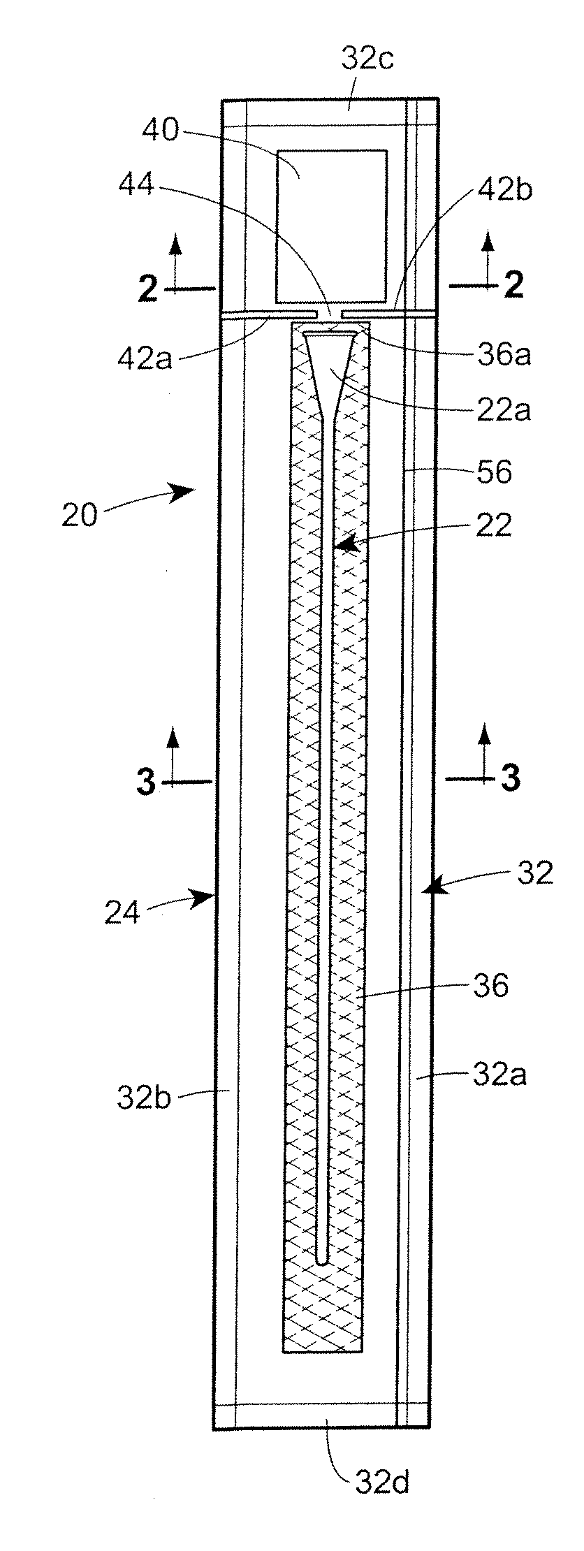
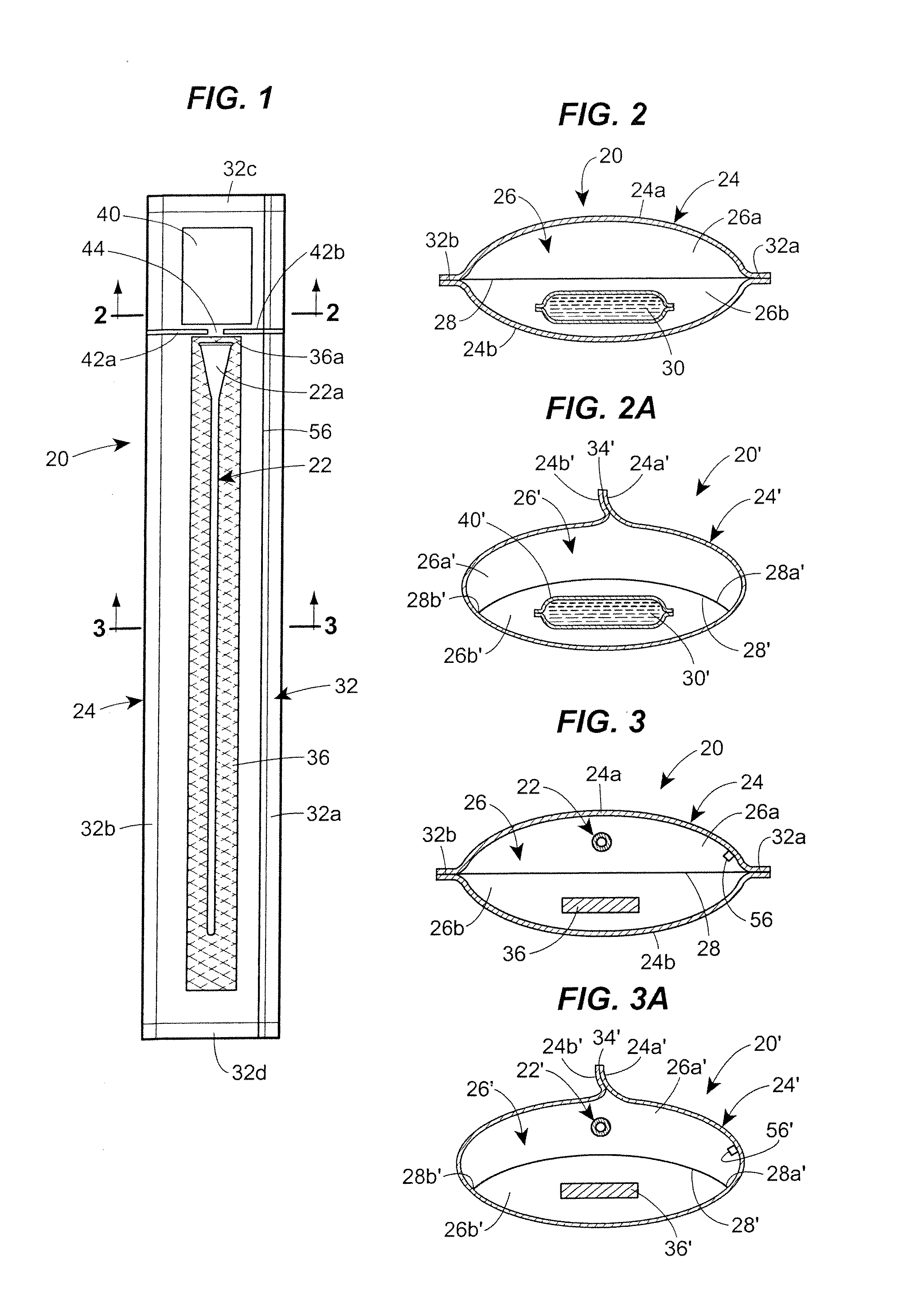
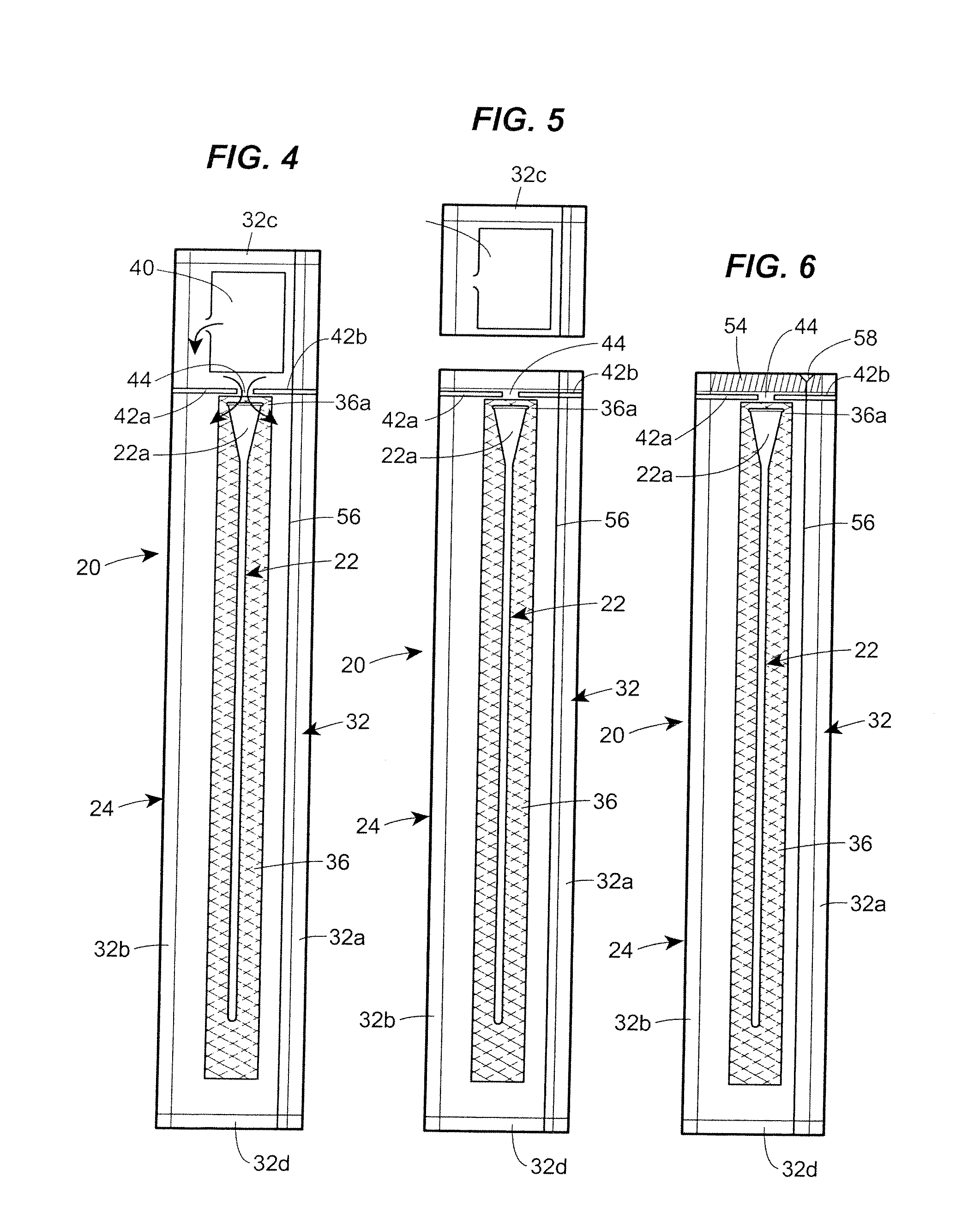
[0052]In the illustrations given herein, and with reference first to FIG. 1, the reference numeral 20 designates generally a vapor hydrated catheter assembly in accordance with one aspect of the disclosure. The catheter assembly 20 comprises a urinary catheter generally designated 22 which has a hydrophilic coating on at least a part of its length intended to produce a low-friction surface on the catheter 22 when treated with a hydrating substance. The catheter assembly 20 also includes a catheter package generally designated 24 which forms an interior space 26 (see, also, FIG. 3) divided by a gas permeable, liquid impermeable barrier 28 into a first cavity 26a and a second cavity 26b. The first cavity 26a accommodates the catheter 22 therein and the second cavity 26b accommodates at least a quantity of vapor donating liquid 30 in its liquid phase such as, e.g., liquid phase water therein. The quantity of liquid phase water 30 may contain, for example, pure liquid water, or any suit...


PUM


Abstract

A catheter assembly and method is disclosed which comprises a catheter having a coating on at least a part of its length intended to produce a low-friction surface on the catheter when treated with an activating substance in the form of a vapor. The catheter assembly also includes a catheter package forming an interior space divided by a gas permeable, liquid impermeable barrier into a first cavity and a second cavity. The first cavity of the catheter package accommodates the catheter therein and the second cavity accommodates at least a quantity of liquid in its liquid phase therein. The liquid in the second cavity can change phase into a vapor capable of passing from the second cavity, through the barrier, and into the first cavity where the vapor can activate the coating. As a result, the vapor produced when the liquid changes phase causes the coating on the catheter to be activated to thereby produce the low-friction surface on the catheter so it is ready-to-use when it reaches the end user.

Description

CROSS REFERENCE TO RELATED APPLICATIONS[0001]This application is a non-provisional application claiming priority to U.S. Provisional Patent Application No. 60 / 988,920, filed on Nov. 19, 2007.FIELD OF THE DISCLOSURE[0002]The present disclosure generally relates to catheter assemblies that are delivered to end users in a ready-to-use condition, and more particularly, to such a catheter assembly that is vapor hydrated and a method of making a vapor hydrated catheter assembly.BACKGROUND OF THE DISCLOSURE[0003]It is generally well known that there are two distinct types of intermittent urinary catheters typically used by those who are able to do so without the assistance of a healthcare professional. These catheters include lubricated catheters which utilize a gel that is applied to the outer surface of the catheter tube prior to insertion into the urethra and hydrophilic catheters wherein a hydrophilic coating on the catheter tube is activated prior to use by treatment with a liquid suc...

Claims


Application Information

Patent Timeline
Patent Type & Authority Applications(United States)
IPC IPC(8): A61M27/00
CPCA61M25/002A61M2025/0062A61M25/0111
Inventor KAVANAGH, SEAMUS T.UDAYAKUMAR, BETTAKERI S.PASSALAQUA, JAMES J.JORGENSEN, KAIGILMAN, THOMAS H.
Owner HOLLISTER INCORPORAED
Why Eureka
Try Eureka