Direct Exchange System Design Improvements

a direct exchange and system design technology, applied in the field of geothermal direct exchange, can solve the problems of inability to achieve conductive heat transfer, and inability to reduce the efficiency of cooling/heating ability, so as to reduce the heating/cooling load requirement and minimize the loss of available cooling/heating ability efficiency

Active Publication Date: 2009-05-28
WIGGS B RYLAND
View PDF11 Cites 17 Cited by
  • Summary
  • Abstract
  • Description
  • Claims
  • Application Information

AI Technical Summary

Benefits of technology

[0011]It is an object of the present disclosures to further enhance and improve at least one of the efficiency, the interior comfort levels, the ease of service and maintenance, the durability, and to reduce the high installation costs, of predecessor direct expansion, geothermal heating / cooling system, designs; as well as to provide unique and improved new DX system applications. In summary, the present disclosures incorporate an R-410A DX heating / cooling system with: an electrical generating expansion device; with a protective means for refrigerant transport tubing containing dissimilar metals and / or in corrosive environments; with an automatic heating mode expansion device; with a TXV by-pass design; with retractable sub-surface tubing designs; with sub-surface line set sizing at varying depths and lengths; with reciprocal compressor sizing; with a DX Hydronic system design; with an improved oil separator float design; with a mobile DX system design; and with a resting module DX system design. The objectives of these disclosures are accomplished as follows:
[0012](1) All heat pump systems use expansion devices, as is well understood by those skilled in the art. Current art expansion devices may be self-adjusting, automatic, fixed pin orifice types, and the like, as is also well understood by those skilled in the art. The object of an expansion device in a heat pumps system application is to maintain a high refrigerant pressure behind the expansion device, and to supply a low pressure refrigerant on the other forward side of the expansion device, so as to reduce both the pressure and the temperature on the low side, so to create a greater temperature differential which enables the circulating refrigerant, circulating within refrigerant transport tubing, to more readily absorb heat from, or to reject heat into, the surrounding environment. Here, “behind” and “forward” of the expansion device designations relate to the directional flow of the heat pump's refrigerant through the expansion device, with “behind” typically consisting of refrigerant flow with higher pressures and with “forward” typically consisting of refrigerant flow with lower pressures.

Problems solved by technology

However, such a plastic coating inhibits conductive heat transfer.
A plastic coating below a 0.01 inch thick wall is too easily compromised via accidental scrapes, or the like, and a plastic coating above a 0.015 inch thick wall can unduly inhibit conductive heat transfer abilities beyond 10% of uncoated metal refrigerant transport tubing.

Method used


Image

  • Direct Exchange System Design Improvements
  • Direct Exchange System Design Improvements
  • Direct Exchange System Design Improvements

Examples


Embodiment Construction

[0084]The following detailed description is of the best presently contemplated mode. The description is not intended in a limiting sense, and is made solely for the purpose of illustrating the general principles of the disclosure. The various features and advantages of the present disclosure may be more readily understood with reference to the following detailed description taken in conjunction with the accompanying drawings.

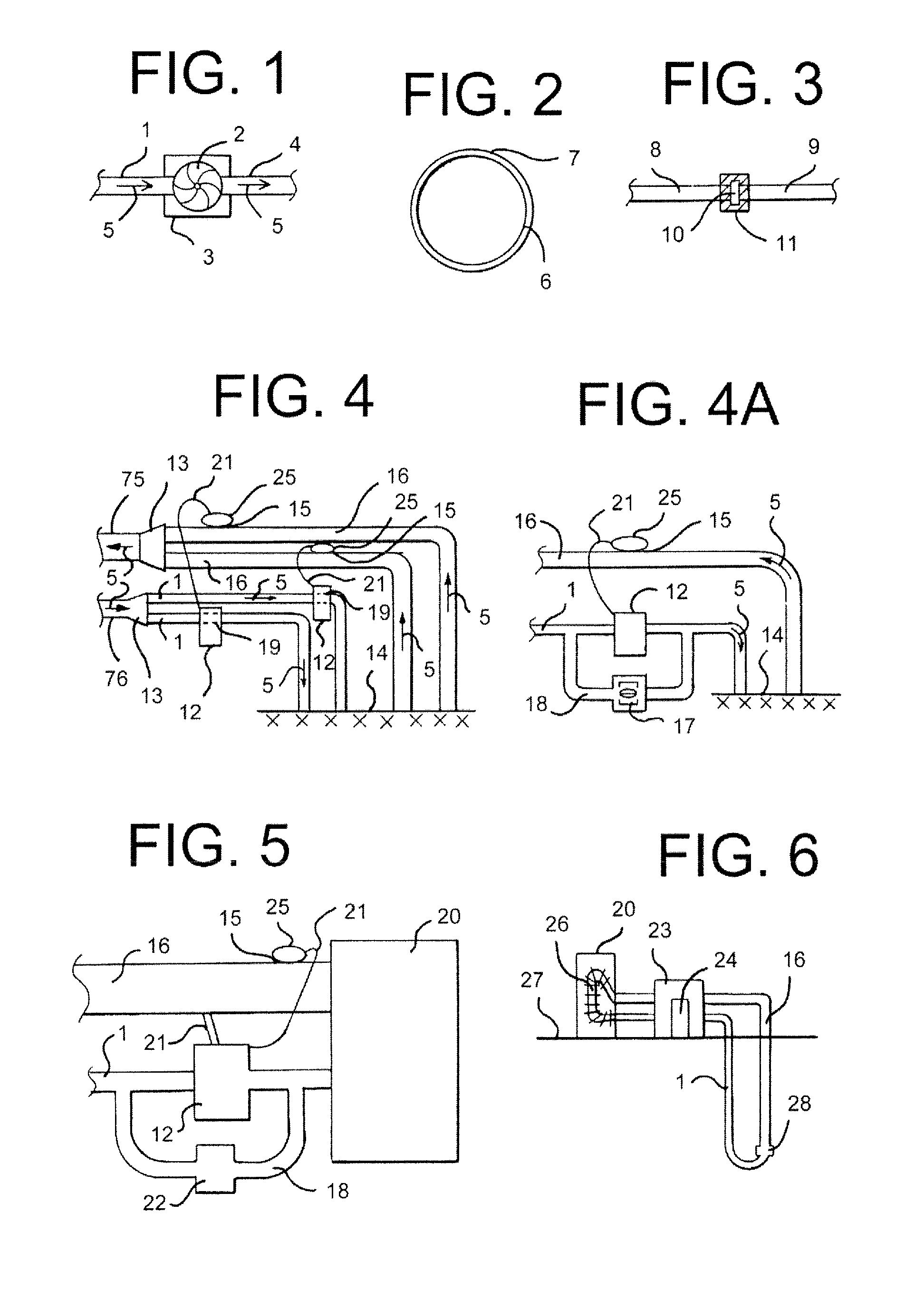
[0085]Referring now to the drawings in detail, where like numerals refer to like parts or elements, there is shown in FIG. 1 a side view of a higher pressure liquid refrigerant transport line 1, coupled to the turbine 2 of an electric generating device 3 (electrical generating devices operated by turbines 2 are well understood by those skilled in the art), which turbine 2 is also coupled to a liquid / vapor refrigerant fluid (not shown except for refrigerant flow directional arrows 5), lower pressure, refrigerant transport line 4. The turbine 2 of the electric gen...


PUM


Abstract

An R-410A DX heating / cooling system with: an electrical generating expansion device; with a protective means for refrigerant transport tubing containing dissimilar metals and / or in corrosive environments; with an automatic heating mode expansion device; with a TXV by-pass design; with retractable sub-surface tubing designs; with sub-surface line set sizing at varying depths and lengths; with reciprocal compressor sizing; with a DX Hydronic system design; with an improved oil separator float design; with a mobile DX system design; and with a resting module DX system design.

Description

CROSS-REFERENCE TO RELATED APPLICATION[0001]This application claims the benefit of U.S. Provisional Application No. 60 / 950,053, filed on Jul. 16, 2007.FIELD OF THE DISCLOSURE[0002]The present disclosure relates to a geothermal direct exchange (“DX”) heating / cooling system comprising various design improvements and various specialty applications.BACKGROUND OF THE DISCLOSURE[0003]Geothermal ground source / water source heat exchange systems typically use fluid-filled closed loops of tubing buried in the ground, or submerged in a body of water, so as to either absorb heat from, or to reject heat into, the naturally occurring geothermal mass and / or water surrounding the buried or submerged fluid transport tubing. The tubing loop is extended to the surface and is then used to circulate one of the naturally warmed and naturally cooled fluid to an interior air heat exchange means.[0004]Common and older design geothermal water-source heating / cooling systems typically circulate, via a water pu...

Claims


Application Information

Patent Timeline
Patent Type & Authority Applications(United States)
IPC IPC(8): F25B27/00F25B30/00F25B41/00
CPCF25B30/06
Inventor WIGGS, B. RYLAND
Owner WIGGS B RYLAND
Why Eureka
Try Eureka