
Apparatuses and Methods to Reduce Safety Risks Associated with Photovoltaic Systems

a photovoltaic system and safety risk technology, applied in the field of photovoltaic systems, can solve the problems of presenting the potential safety risks associated with presenting its own safety risk, and presenting the potential safety risks of working in a poorly lit environment, so as to reduce the safety risks

Active Publication Date: 2009-05-28
NEWLIGHT CAPITAL LLC
View PDF47 Cites 167 Cited by
  • Summary
  • Abstract
  • Description
  • Claims
  • Application Information

AI Technical Summary

Benefits of technology

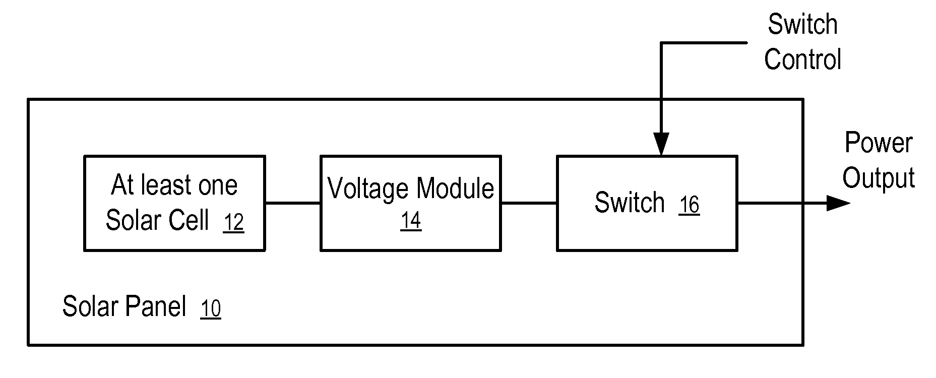
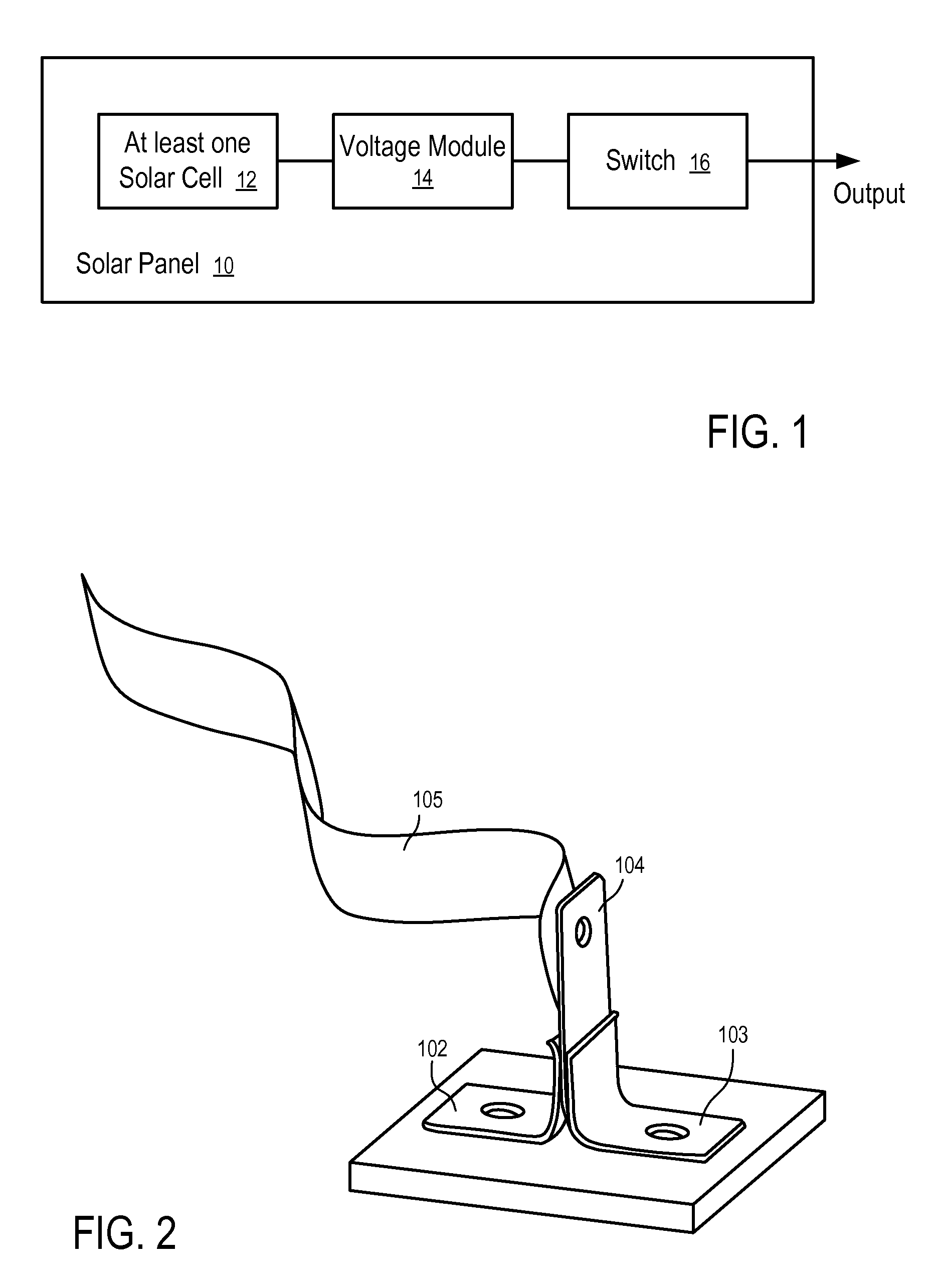
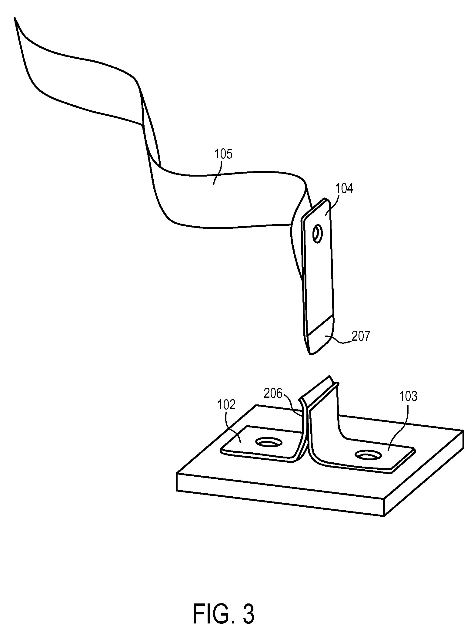
"The patent describes a safety switch for photovoltaic systems that reduces safety risks. The switch is connected between the photovoltaic cells and the connector of the panel, and it disconnects the cells from the connector during installation. The switch includes a removable portion that connects the cells with the connector after installation. The switch can be controlled by an optical sensor, a reed switch, a semiconductor switch, a relay, or an alternating current output. The patent also describes a photovoltaic panel module that includes a voltage module to adjust the output of the cells and a switch to selectively provide the output. The module can also include connectors to control the switch. The technical effects of the patent include improved safety and reliability of photovoltaic systems."

Problems solved by technology

When a photovoltaic panel or laminate is exposed to direct or diffuse light, a lethal voltage potential may be present.
However, this approach proposes its own safety risk from having the wind catch the tarpaulin and pull installation personnel off the roof as they try to control the unstable sheet material against the wind.
This approach presents the potential safety risks associated from working in a poorly lighted environment.
In addition to the potential personnel safety issues there are also significant risks to equipment and hardware.
Connecting or disconnecting energized plugs can cause arcing and damage to these connectors, junction boxes, and other electrical components.

Method used


Image

  • Apparatuses and Methods to Reduce Safety Risks Associated with Photovoltaic Systems
  • Apparatuses and Methods to Reduce Safety Risks Associated with Photovoltaic Systems
  • Apparatuses and Methods to Reduce Safety Risks Associated with Photovoltaic Systems

Examples


Embodiment Construction

[0028]The following description and drawings are illustrative and are not to be construed as limiting. Numerous specific details are described to provide a thorough understanding. However, in certain instances, well known or conventional details are not described in order to avoid obscuring the description. References to one or an embodiment in the present disclosure are not necessarily references to the same embodiment; and, such references mean at least one.

[0029]One embodiment of the disclosure provides a method and system to reduce the safety risks during the shipment, installation and / or maintenance of photovoltaic systems, without introducing the risks associated with other approaches, such as covering them with an opaque material or working on them at night.

[0030]In one embodiment, safety protection is provided via the inclusion of a normally closed switch integral to the panel junction box or integral to the panel module when alternating current (AC) or direct current (DC) m...


PUM


Abstract

Apparatuses and methods to reduce safety risks associated with photovoltaic systems by providing a safety switch on a photovoltaic panel. In one embodiment, a photovoltaic panel includes: at least one photovoltaic cell; a connector to output energy from the photovoltaic panel; and a switch coupled between the at least one photovoltaic cell and the connector. The switch is configured to disconnect the at least one photovoltaic cell from the connector during installation of the photovoltaic panel, and to connect the at least one photovoltaic cell with the connector after installation of the photovoltaic panel.

Description

RELATED APPLICATIONS[0001]The present application is a continuation application of a copending U.S. patent application Ser. No. 12 / 254,780, filed Oct. 20, 2008, which claims priority to provisional U.S. Patent Application Ser. No. 61 / 001,587, filed on Nov. 2, 2007 and entitled “Photovoltaic Safety Switch.” The disclosures of the above referenced applications are hereby incorporated herein by reference.FIELD OF THE TECHNOLOGY[0002]At least some embodiments disclosed herein relate to photovoltaic systems in general and, more particularly but not limited to, safety devices for the shipment, installation and / or maintenance of photovoltaic systems.BACKGROUND[0003]When a photovoltaic panel or laminate is exposed to direct or diffuse light, a lethal voltage potential may be present. In the United States the possible voltage could be as high as 600 volts, while in Europe and the rest of the world this voltage could approach a kilovolt.[0004]Because of this potential danger from electrical s...

Claims


Application Information

Patent Timeline
Patent Type & Authority Applications(United States)
IPC IPC(8): H01L31/042
CPCY02E10/50H02S40/34H01L31/02021
Inventor POWELL, EARL G.HADAR, RONKIKINIS, DANARDITI, SHMUEL
Owner NEWLIGHT CAPITAL LLC
Learn More