
Vehicle health monitoring system architecture for diagnostics and prognostics disclosure

a technology for health monitoring and vehicle health, applied in the direction of process and machine control, instruments, navigation instruments, etc., to facilitate the operation of monitoring, diagnostics and health maintenance, and facilitate the receipt of preliminary outputs

Active Publication Date: 2009-05-28
HONEYWELL INT INC
View PDF9 Cites 42 Cited by
  • Summary
  • Abstract
  • Description
  • Claims
  • Application Information

AI Technical Summary

Benefits of technology

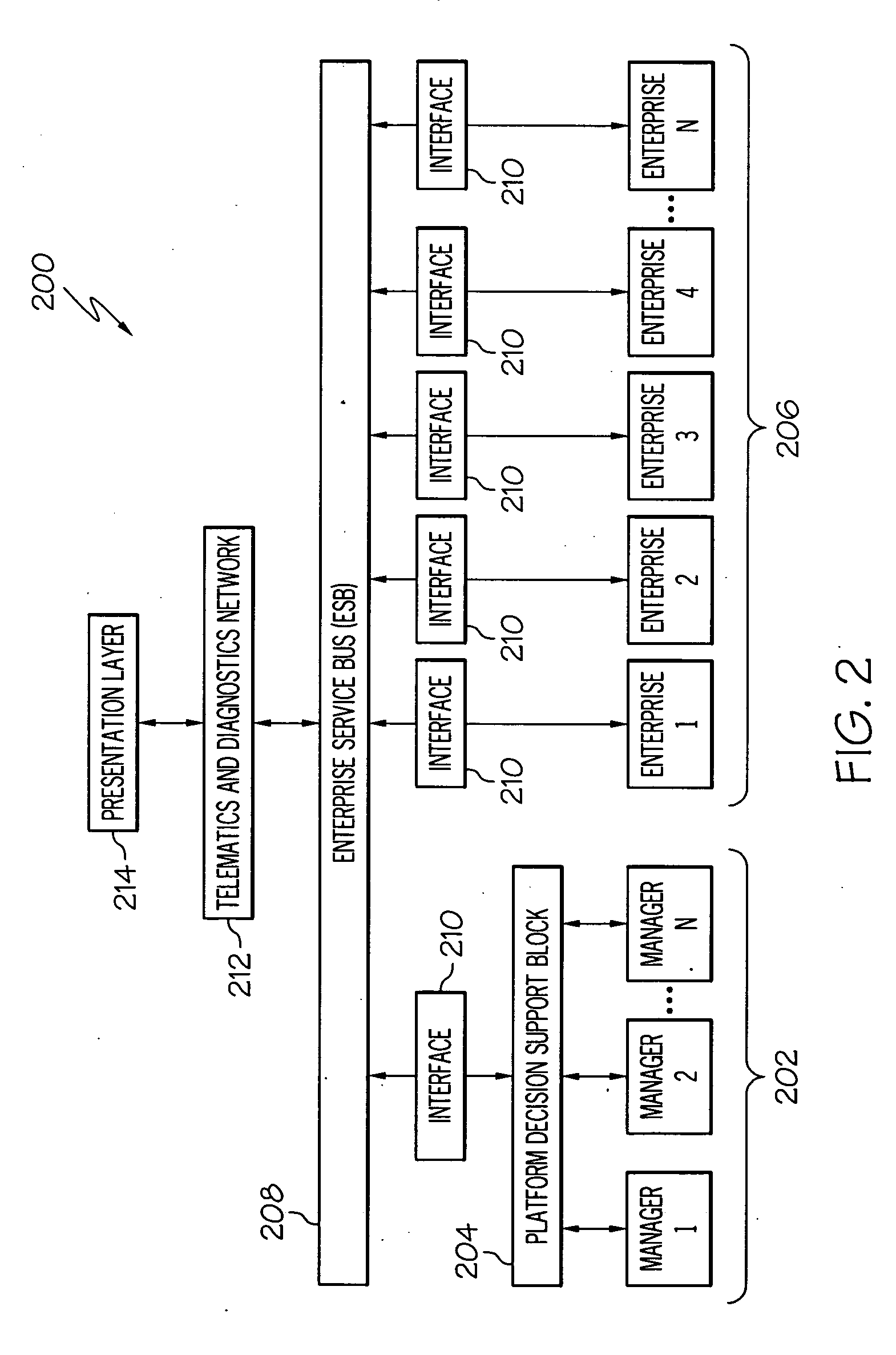
The present invention provides a hierarchical architecture for monitoring, diagnostics, and predictive health management of a vehicle system. The system includes a health management and operational support system comprising multiple managers and a decision support module. Each manager is responsible for monitoring and managing the health of a different major system of the vehicle. The manager has a plurality of reasoners, which obtain fault monitoring results from components of the subsystem and provide diagnosis and predictive monitoring of the subsystem. The reasoners are connected to a fusion block, which generates a manager output based on the preliminary output from the reasoners. The decision support module receives the manager output and provides a decision support output based on the manager output. The computer system includes a computer software program and a computer system for performing health monitoring, diagnostics, and predictive health management on a vehicle system.

Problems solved by technology

However, such health monitoring systems often have a support system or architecture that was developed on an ad hoc basis Such architectures may not provide optimal and streamlined support for diagnostics and prognostics pertaining to the vehicle that a hierarchal architecture discussed here would provide.

Method used


Image

  • Vehicle health monitoring system architecture for diagnostics and prognostics disclosure
  • Vehicle health monitoring system architecture for diagnostics and prognostics disclosure
  • Vehicle health monitoring system architecture for diagnostics and prognostics disclosure

Examples


Embodiment Construction

[0022]The following detailed description of the invention is merely exemplary in nature and is not intended to limit the invention or the application and uses of the invention. Furthermore, there is no intention to be bound by any theory presented in the preceding background of the invention or the following detailed description of the invention.

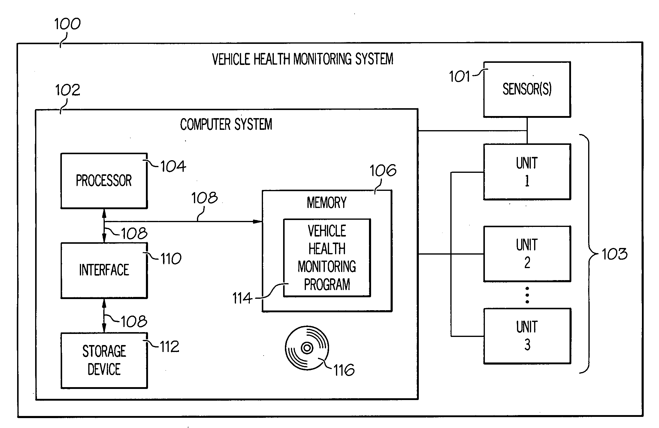
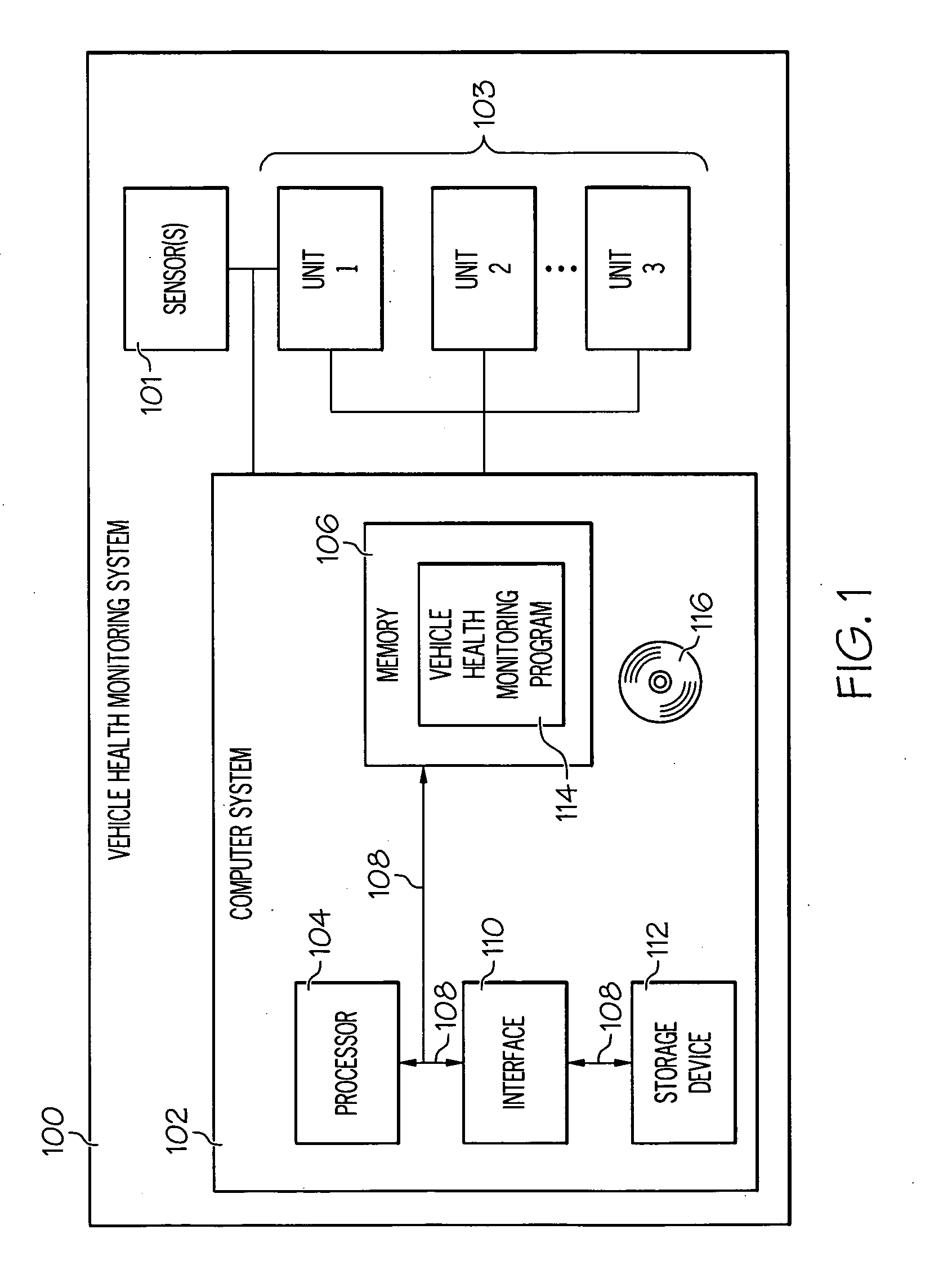
[0023]FIG. 1 is a functional block drawing of a vehicle health monitoring system 100, in accordance with an exemplary embodiment of the present invention. In the depicted embodiment, the vehicle health monitoring system 100 includes one or more sensors 101, a computer system 102 and a plurality of additional units 103. However, this may vary in other embodiments.

[0024]The one or more sensors 101 are preferably coupled to the vehicle and / or one or more components or systems thereof. The sensors 101 preferably at least facilitate generation of engine data pertaining to operation of the engine and / or one or more systems and / or sub-systems of th...


PUM


Abstract

A health monitoring system for a vehicle system includes an operational support system including a plurality of managers and a decision support module. Each manager corresponds to a different sub-system of the vehicle system, and comprises a plurality of reasoners and a fusion block. Each reasoner is configured to obtain data and provide preliminary output regarding a different component of the sub-system based on the data. The fusion block is coupled to the plurality of reasoners, and is configured to receive the preliminary output and generating manager output based on the preliminary output. The decision support module is coupled to the plurality of managers, and is configured to receive the manager output and provide a decision support output based on the manager output.

Description

CROSS-REFERENCE TO RELATED APPLICATION[0001]This application claims the benefit of U.S. Provisional Application No. 60 / 990,195, filed Nov. 26, 2007.TECHNICAL FIELD[0002]The operational health of a vehicle system needs to be monitored and predicted to insure the vehicle is available to perform its required functions at any point in time. Such a vehicle comprising major operational systems; the major operational systems comprising subsystems, components and sensors. The present invention generally relates to health monitoring systems for such vehicles and, more particularly, to an architecture for health monitoring systems for performing diagnostics and prognostics on vehicles.[0003]One embodiment of such a vehicle is an aircraft whose major operational system examples are its propulsion system, its environment control system, its landing system, its flight control system, its ground proximity monitoring system etc. These major operational systems within the aircraft comprise operatio...

Claims


Application Information

Patent Timeline
Patent Type & Authority Applications(United States)
IPC IPC(8): G06F19/00
CPCG07C5/085G07C5/0808
Inventor NWADIOGBU, EMMANUEL OBIESIEMYLARASWAMY, DINKARMENON, SUNILHADDEN, GEORGE
Owner HONEYWELL INT INC
Learn More