
Coding device and coding method

a coding device and coding technology, applied in the direction of coding, channel coding adaptation, code conversion, etc., can solve the problems of packet retransmission posing the problem of delay time, packet retransmission may not be saved, and packet retransmission may not be discarded or lost during transmission, so as to secure the quality of decoded image and audio. , the effect of constant transfer ra

Inactive Publication Date: 2009-05-28
FUJITSU LTD
View PDF6 Cites 53 Cited by
  • Summary
  • Abstract
  • Description
  • Claims
  • Application Information

AI Technical Summary

Benefits of technology

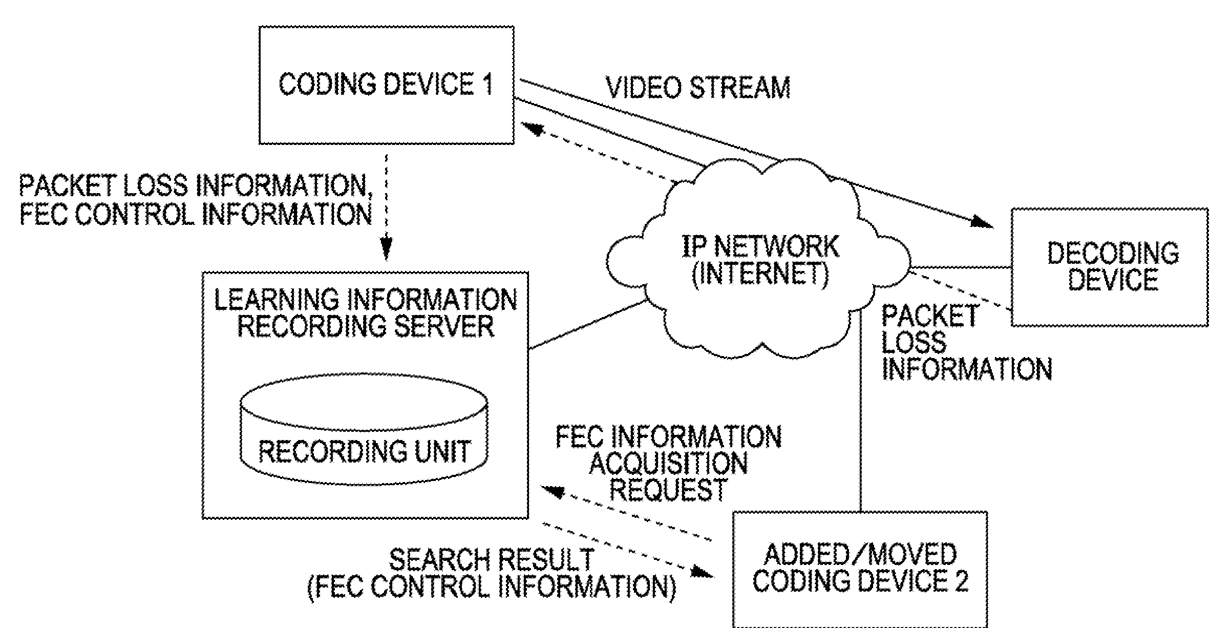
[0016]There are a number of issues with the conventional methods described above. In order to secure a constant transfer rate with consideration for the processing load and the situation of the network connecting the transmitting and receiving ends, it is desirable to appropriately select a method suitable for the situation and the processing load of the network and intervals at which an FEC packet is inserted in each method. Typically, in a real-time IP transmission of video and audio signals, a compressed stream is transmitted as RTP (real-time transport protocol) pac

Problems solved by technology

Hence, packets may be discarded or lost during transmission due to traffic of the repeater network, buffer overflows in the repeaters, and / or physical or electrical data error.
Accordingly, the packet is retransmitted when lost, and therefore, the packet retransmission poses the problem of a delay time.
However, continuous packet loss may not be saved (the loss of two or more packets in the plurality of IP packets used for generating one FEC packet cannot be restored).
Therefore, although the resistance to the loss of continuous two packets is high, the delay is great due to the increase in buffer amount for decoding at the receiving end.
Thus, the amount of buffer operation for decoding at the receiving end is increased, and therefore, the delay is increased.
There are a number of issues with the conventional methods described above.
The conventional techniques described above, however, pose a challenge to select an appropriate method of generating and inserting an FEC packet.
Thus, it is difficult to select an appropriate method of generating and inserting an FEC packet.

Method used


Image

  • Coding device and coding method
  • Coding device and coding method
  • Coding device and coding method

Examples


Embodiment Construction

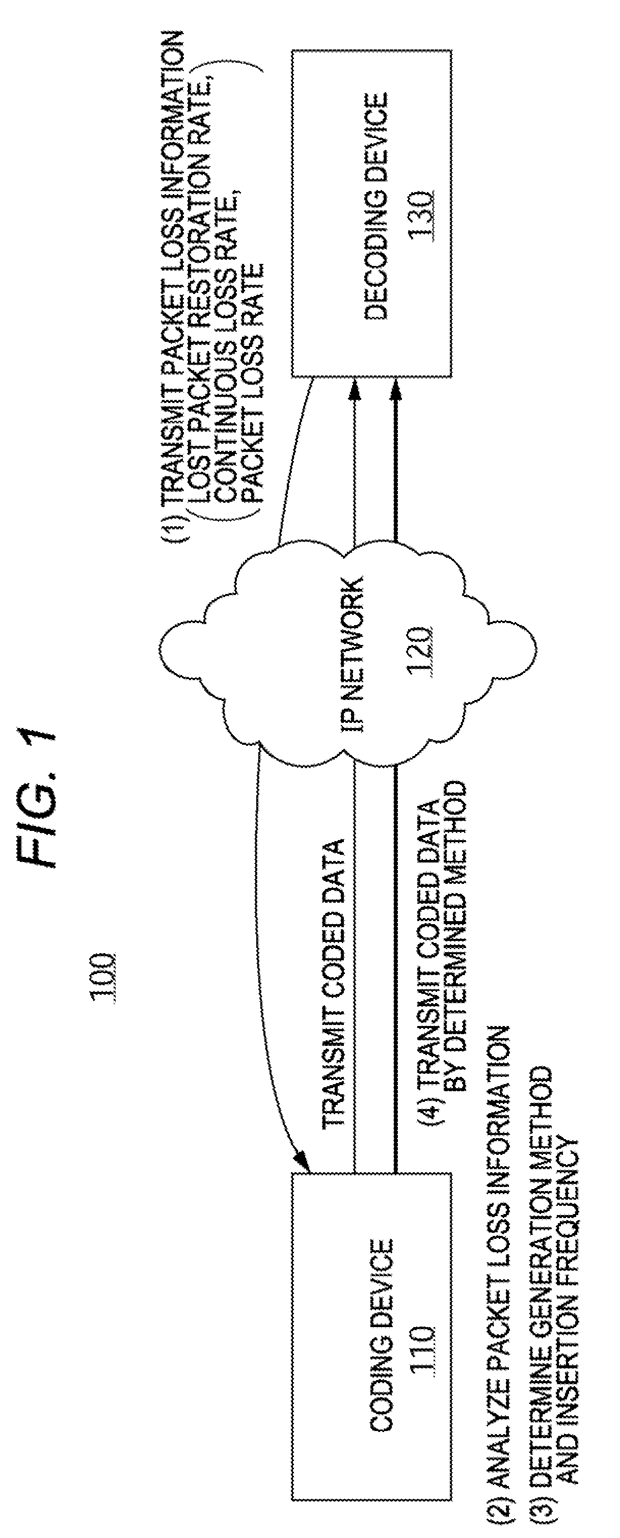
[0039]FIG. 1 illustrates a general configuration of a system 100 including a coding device and a decoding device according to an embodiment. As shown, the system 100 includes a coding device 110 for transmitting a bit string of compression-coded video and audio data as a packet and a decoding device 130 for generating original data by decoding the received coded data, connected to each other through a data network 120, which may be an IP network such as the Internet, an intranet, or any other public or private data network.

[0040]The coding device 110 shown here, for example, is a MPEG coding device for retrieving image and audio from a camera and a microphone, respectively, installed at a place to be monitored and transmitting a compression-coded bit string as a UDP packet to the decoding device 130 through the Internet 120. In this system, a remote place is monitored in real time by decoding the data and reproducing the decoded data through a monitor and a speaker at the side of th...


PUM


Abstract

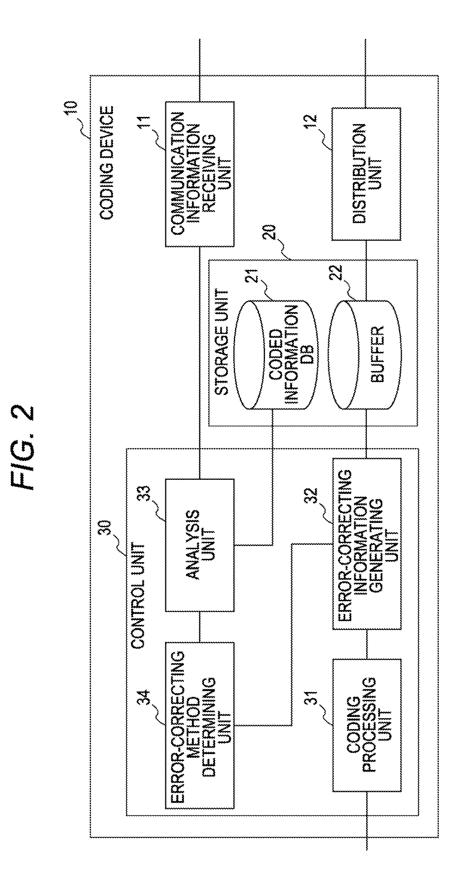
A coding method to code original data and transmit the coded data as a plurality of data packets to a destination, the coding method comprising: receiving packet loss information associated with the transmission of at least some of the plurality of data packets, the packet loss information including a lost packet restoration rate, a continuous packet loss rate and a packet loss rate of the packets transmitted to the decoding device; and generating an error-correcting redundant packet and inserting the error-correcting redundant packet in subsequent ones of the plurality of data packets for transmission to the destination based on the received packet loss information.

Description

CROSS-REFERENCE TO RELATED APPLICATIONS[0001]This application is based upon and claims the benefit of priority of the prior Japanese Application No. 2007-294890, filed on Nov. 13, 2007, the entire contents of which are incorporated herein by reference.BACKGROUND[0002]1. Field[0003]The invention relates to a coding method and a coding device for transmitting a bit string of coded data as a packet to a decoding device, which is employed to generate original data by decoding compression-coded video and audio data.[0004]2. Description of the Related Art[0005]Conventionally, as shown in FIG. 13, a system for monitoring a remote place in real time is generally used, in which an image or video picked up by a camera and audio picked up by a microphone installed at a place to be monitored are transduced into electrical signals and forwarded to a MPEG (Moving Picture Experts Group) coding device, which further codes the received signals into a compression-coded bit string for transmission as ...

Claims


Application Information

Patent Timeline
IPC IPC(8): H03M13/05G06F11/10H04L1/00H04N19/00H04N19/102H04N19/164H04N19/166H04N19/172H04N19/177H04N19/65H04N19/67H04N19/70
CPCH03M13/353H03M13/373H04L2001/0097H04L1/0009H04L1/0026H03M13/6547
Inventor TAMURA, HIROKIDOI, KAZUMIOHSAKI, YOSHIYAENDOH, JUNHARA, KANNA
Owner FUJITSU LTD
Learn More