

Downhole swaging system and method
a swaging system and downhole technology, applied in the direction of fluid removal, sealing/packing, borehole/well accessories, etc., can solve the problem of setting eventually failing, and achieve the effect of different resistance to swaging
- Summary
- Abstract
- Description
- Claims
- Application Information
AI Technical Summary
Benefits of technology
Problems solved by technology
Method used
Image

Examples
Embodiment Construction
[0013]A detailed description of several embodiments of the disclosed apparatus and method are presented herein by way of exemplification and not limitation with reference to the Figures.
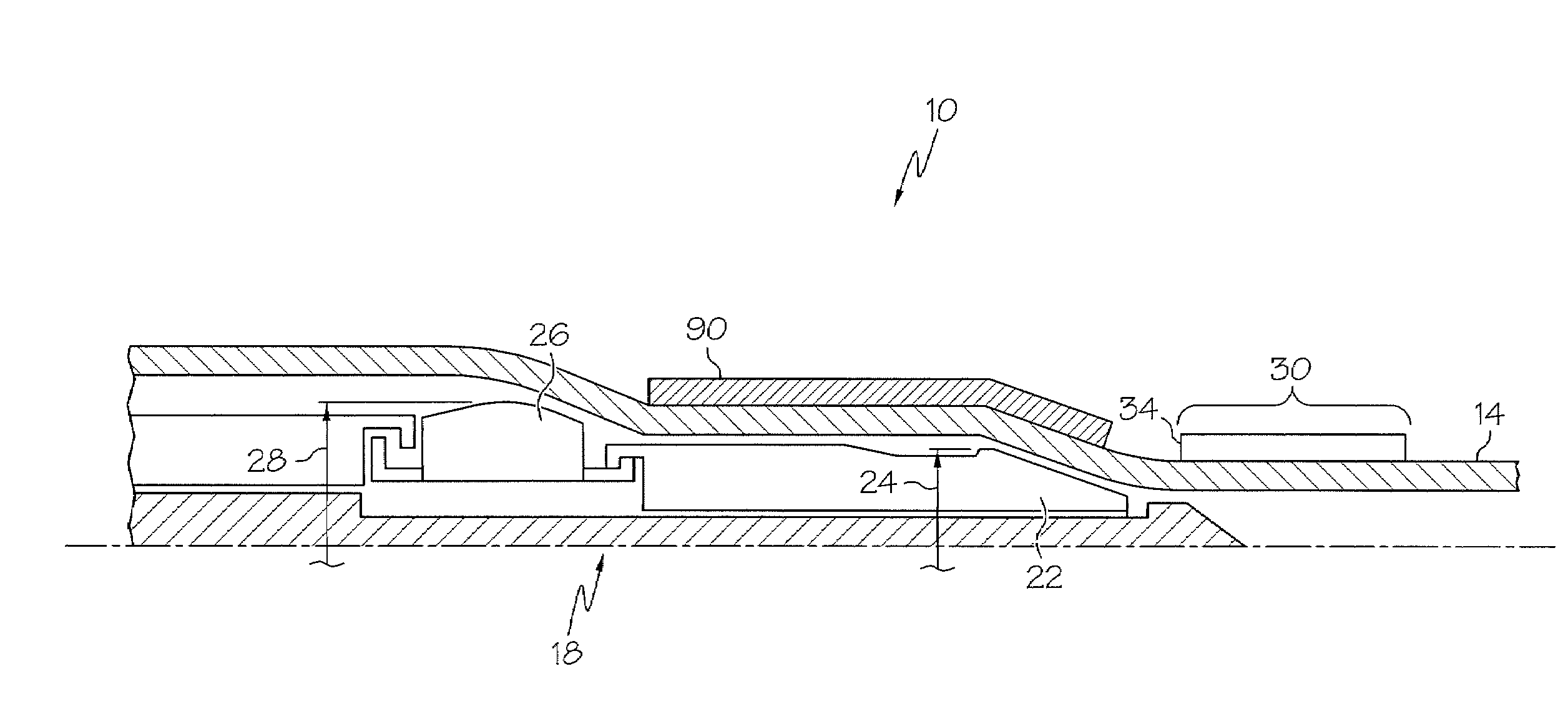
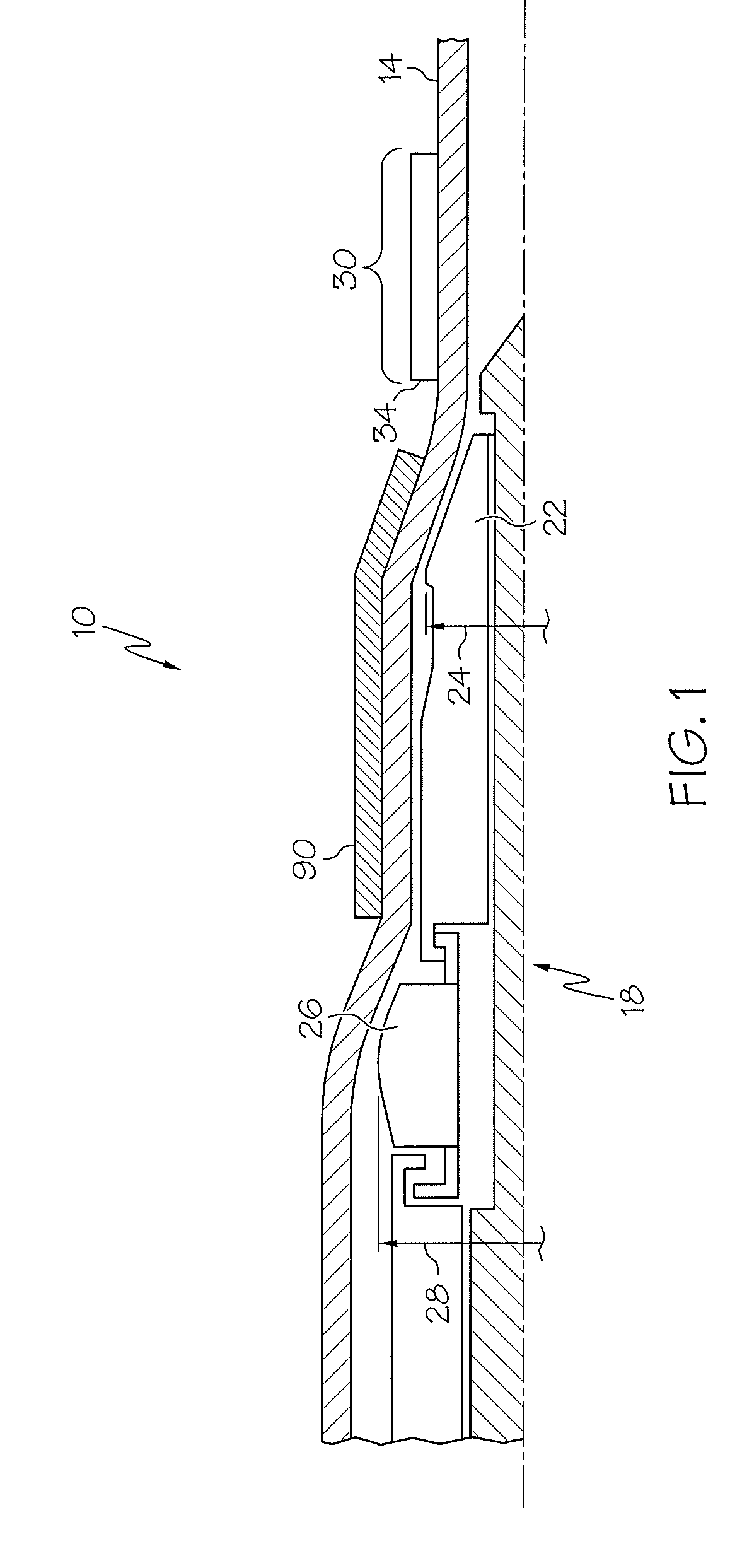
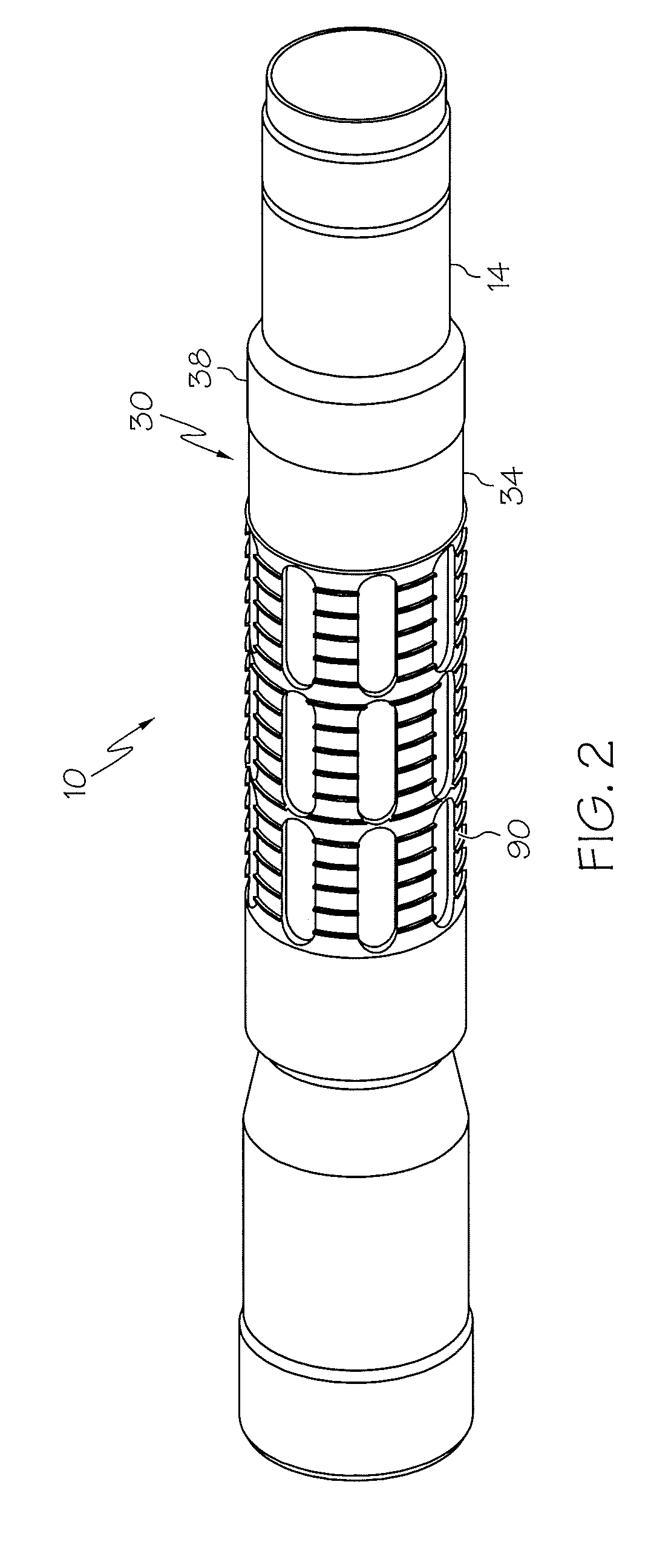
[0014]Referring to FIGS. 1 and 2, an embodiment of the downhole swaging system 10 disclosed herein is illustrated. The swaging system 10, among other things, includes a swagable tubular 14, depicted herein as a liner made of a rigid material such as steel, for example, and a swaging tool 18. The swaging tool 18 has a first swage 22 that, in this embodiment, has a fixed first swaging dimension 24, and a second swage 26 that has an adjustable second swaging dimension 28. It should be noted that alternate embodiments might have a first swage that is adjustable such that the first swage would have an adjustable swaging dimension that could at times exceed the swaging dimension 24. The tubular 14 has an area of strength 30, depicted in this embodiment as a load ring 34 positioned coaxially with the tubula...
PUM
 Abstract
Description
Claims
Application Information