Octupole winding pattern for a fiber optic coil

a fiber optic coil and octupole winding technology, applied in the direction of cladded optical fiber, instruments, transportation and packaging, etc., can solve the problems of differential phase shift, affecting counter-propagating waves, and refractive index change,

Inactive Publication Date: 2009-06-04
AIR FORCE UNITED STATES
View PDF3 Cites 4 Cited by
  • Summary
  • Abstract
  • Description
  • Claims
  • Application Information

AI Technical Summary

Problems solved by technology

These factors or asymmetries, as well as others, may cause a refractive index change and thus affect the counter-propagating waves.
Consequently, one result of the environmentally-induced factors and / or asymmetries is that a differential phase shift will occur that inaccurately mimics a sensed rotation of the fiber optic gyroscope.
One drawback of the conventional octupole pattern is that urging the full diameter of the fiber optic coil into the half diameter space may cause a hump or bulge to form in the wound fiber optic coil.
Correspondingly, the hump or bulge may often result in both geometric and mechanical asymmetries, which may reduce the performance and / or accuracy of the fiber optic gyroscope.

Method used


Image

  • Octupole winding pattern for a fiber optic coil
  • Octupole winding pattern for a fiber optic coil
  • Octupole winding pattern for a fiber optic coil

Examples


Embodiment Construction

[0014]In the following description, certain specific details are set forth in order to provide a thorough understanding of various embodiments of the invention. However, one skilled in the art will understand that the invention may be practiced without these details or with various combinations of these details. In other instances, well-known structures and methods associated with fiber optic gyroscopes, fiber optic coils, fiber optic coils arranged in an octupole pattern and integrated circuit (IC) chips, to include the manufacturing and / or assembly thereof may not be shown or described in detail to avoid unnecessarily obscuring descriptions of the embodiments of the invention.

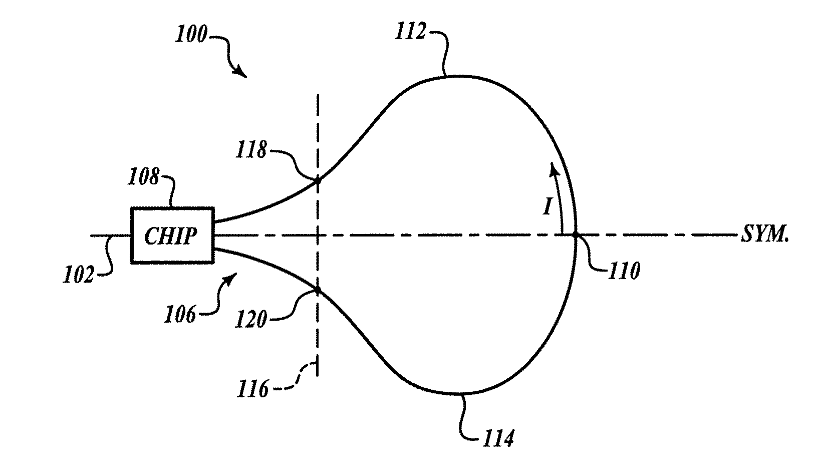
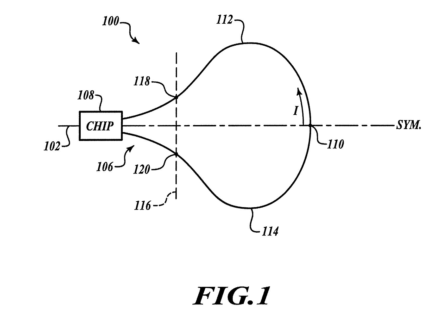
[0015]The following description is generally directed to an octupole pattern for a fiber optic coil, for example a fiber optic coil that may be used in a fiber optic gyroscope. Preferably, the octupole pattern substantially reduces asymmetries in sections of the fiber optic coil that may have an effect on the...


PUM


Abstract

An octupole winding pattern for winding a fiber optic coil includes at least two layers of an eight-layer winding pattern having an end fiber optic coil diameter formed in an opposite direction as a substantial portion of a remaining portion of the respective layer. The selectively arranged octupole winding pattern may be used in a fiber optic gyroscope. A spool onto which the fiber optic coil is wound may be removable. Preferably, the octupole winding pattern is advantageously arranged to provide a substantial amount of optical symmetry with respect to a winding centerline of the fiber optic coil. In addition, the octupole winding pattern provides a substantial amount of geometric, mechanical, and thermal symmetry.

Description

GOVERNMENT RIGHTS[0001]The United States Government has acquired certain rights in this invention pursuant to Contract No. FA9453-06-C-0097 issued by the United States Air Force.BACKGROUND OF THE INVENTION[0002]An interferometric fiber optic gyroscope typically includes a single mode, continuous fiber optic coil formed in a conventional octupole pattern such that light is guided through the coil to manifest the Sagnac effect. A conventional octupole pattern for winding a fiber optic coil is appreciated as a winding pattern where the pattern repeats itself every eight (8) layers. Conventional octupole winding patterns are generally known in the gyroscopic arts and are further known to place at least some amount of stress on the fiber optic coil in various regions of the pattern.[0003]The Sagnac effect is generally understand to be when two counter propagating light beams, one traveling clockwise (CW) and the other traveling counterclockwise (CCW) and both generated from the same sour...

Claims


Application Information

Patent Timeline
Patent Type & Authority Applications(United States)
IPC IPC(8): G01C19/72G02B6/02B65H18/08
CPCG02B6/4457G01C19/722
Inventor SARDINHA, MIKERIVERA, JOSEPHKALISZEK, ANDREWKOPACZ, STANISLAW
Owner AIR FORCE UNITED STATES
Why Eureka
Try Eureka