Eureka AIR delivers breakthrough ideas for toughest innovation challenges, trusted by R&D personnel around the world.

Apparatus and method for handling fluids at nano-scale rates

a nano-scale rate and fluid technology, applied in the direction of positive displacement liquid engines, piston pumps, laboratory glassware, etc., can solve the problems of inability to mix concentration gradients and particularly continuous gradients, limited number of concentrations measured, and technologic limitations, so as to minimize out-of-phase thermal pumping, minimize temperature differences, and minimize thermal pumping

Active Publication Date: 2009-06-04
SCIEX
View PDF12 Cites 8 Cited by
  • Summary
  • Abstract
  • Description
  • Claims
  • Application Information

AI Technical Summary

Benefits of technology

This patent describes how to control the temperatures of different parts in a group of pumps that work together. By measuring the temperature of these parts regularly, this system helps prevent them from causing problems with each other's performance. It does this by adjusting the temperature settings on individual pumps until they are all running smoothly without excessive heat output.

Problems solved by technology

The technical problem addressed in this patent text relates to improving the design of microfluidic systems by considering various methods of generating movement and achieving steady, precise, controllable flow rates. Current options for pneumatic and electricity-based pumps tend to have limited capabilities, while serumotropic pumps require high costs and cannot easily adjust for changing needs. Microcfluidic interconnects must also be carefully considered to ensure efficient transfer of liquids without introducing unwanted delays or trapping bubbles. To solve these issues, new approaches based on principle discovery and experimentation are needed.

Method used


Image

  • Apparatus and method for handling fluids at nano-scale rates
  • Apparatus and method for handling fluids at nano-scale rates
  • Apparatus and method for handling fluids at nano-scale rates

Examples


Embodiment Construction

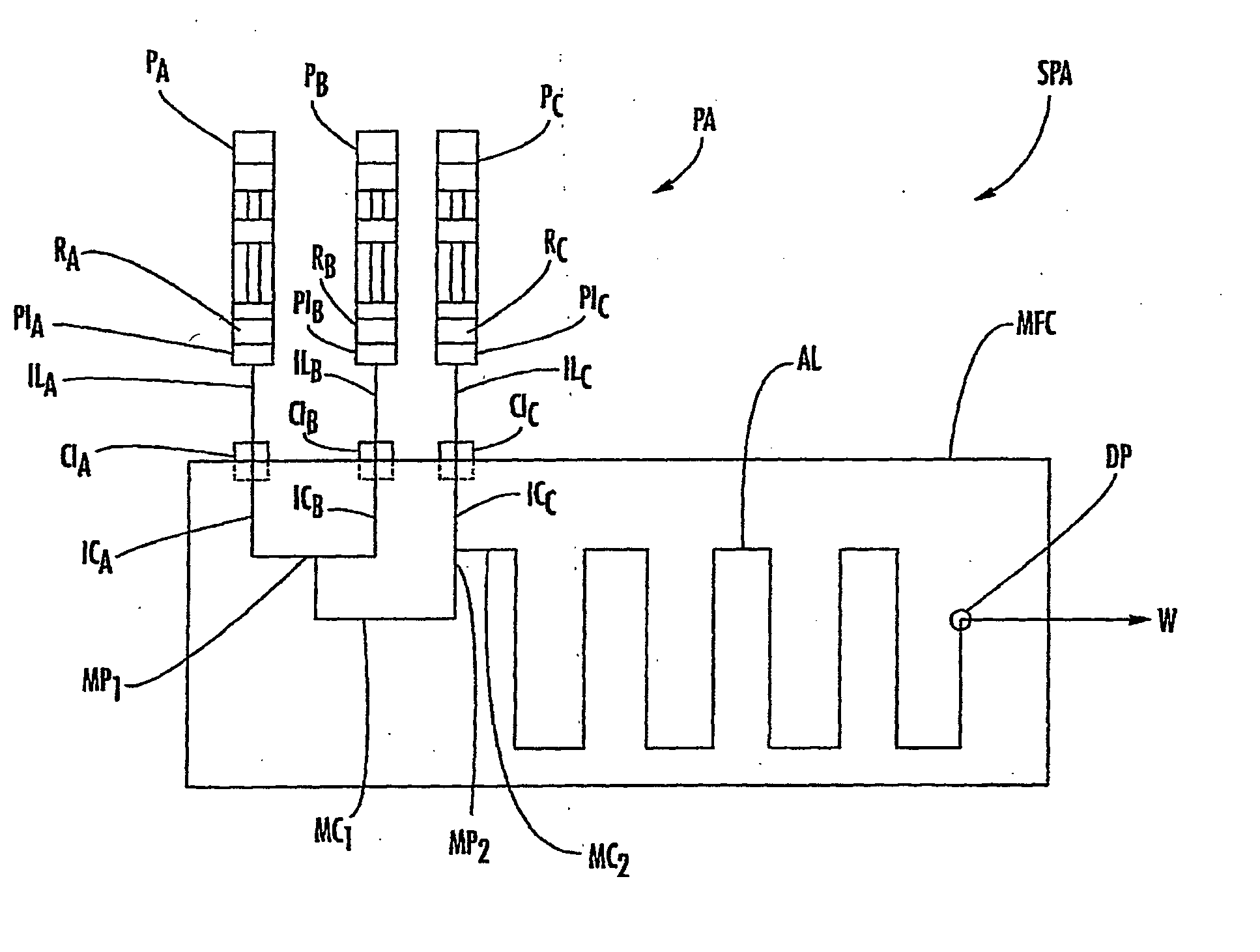
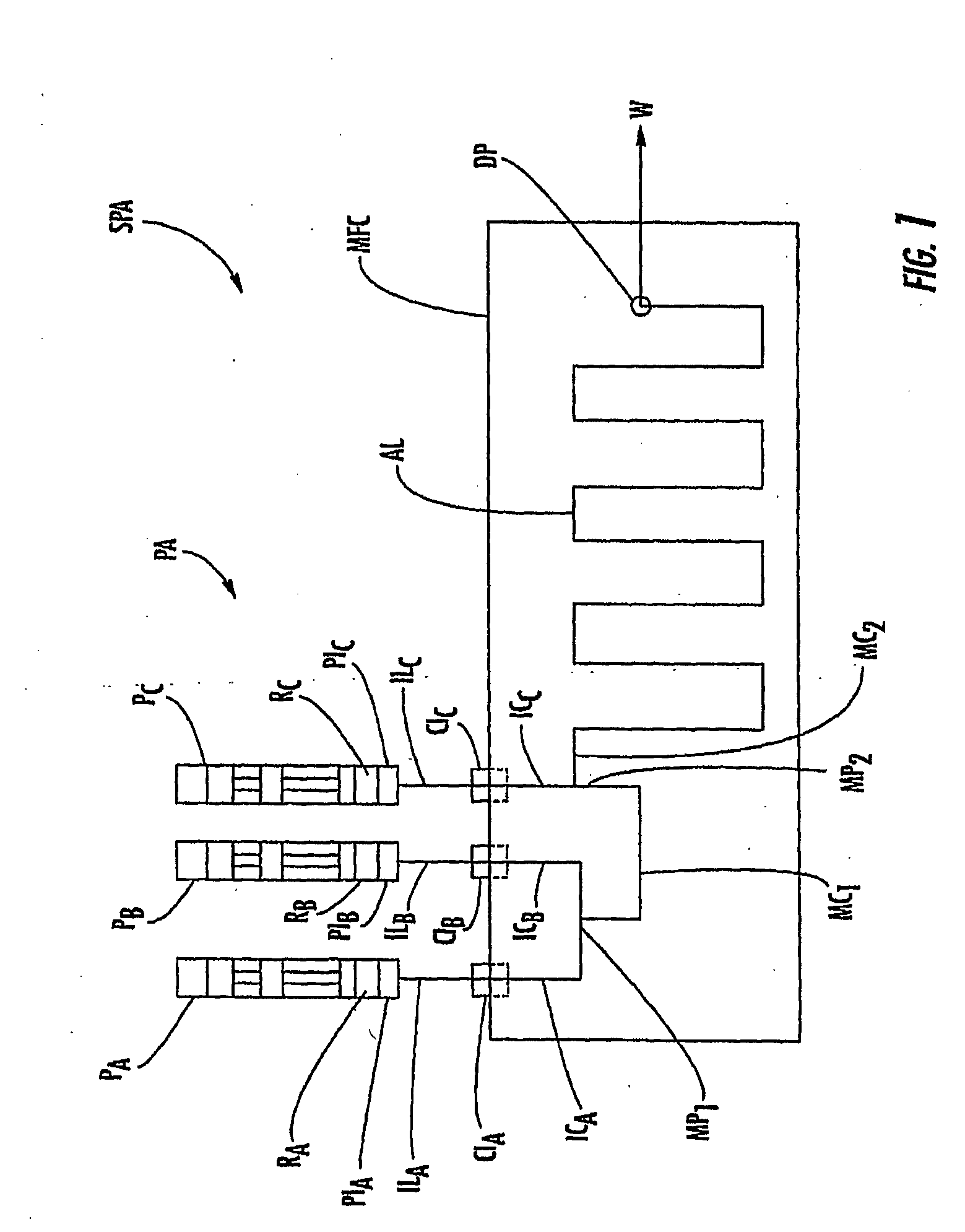
[0048]Microfluidic chips, systems, and related methods are described herein which incorporate improvements for reducing or eliminating noise in the fluid mix concentration. These microfluidic chips, systems, and methods are described with regard to the accompanying drawings. It should be appreciated that the drawings do not constitute limitations on the scope of the disclosed microfluidic chips, systems, and methods.

[0049]As used herein, the term “microfluidic chip,”“microfluidic system,” or “microfluidic device” generally refers to a chip, system, or device which can incorporate a plurality of interconnected channels or chambers, through which materials, and particularly fluid borne materials can be transported to effect one or more preparative or analytical manipulations on those materials. A microfluidic chip is typically a device comprising structural or functional features dimensioned on the order of mm-scale or less, and which is capable of manipulating a fluid at a flow rate ...


PUM


Abstract

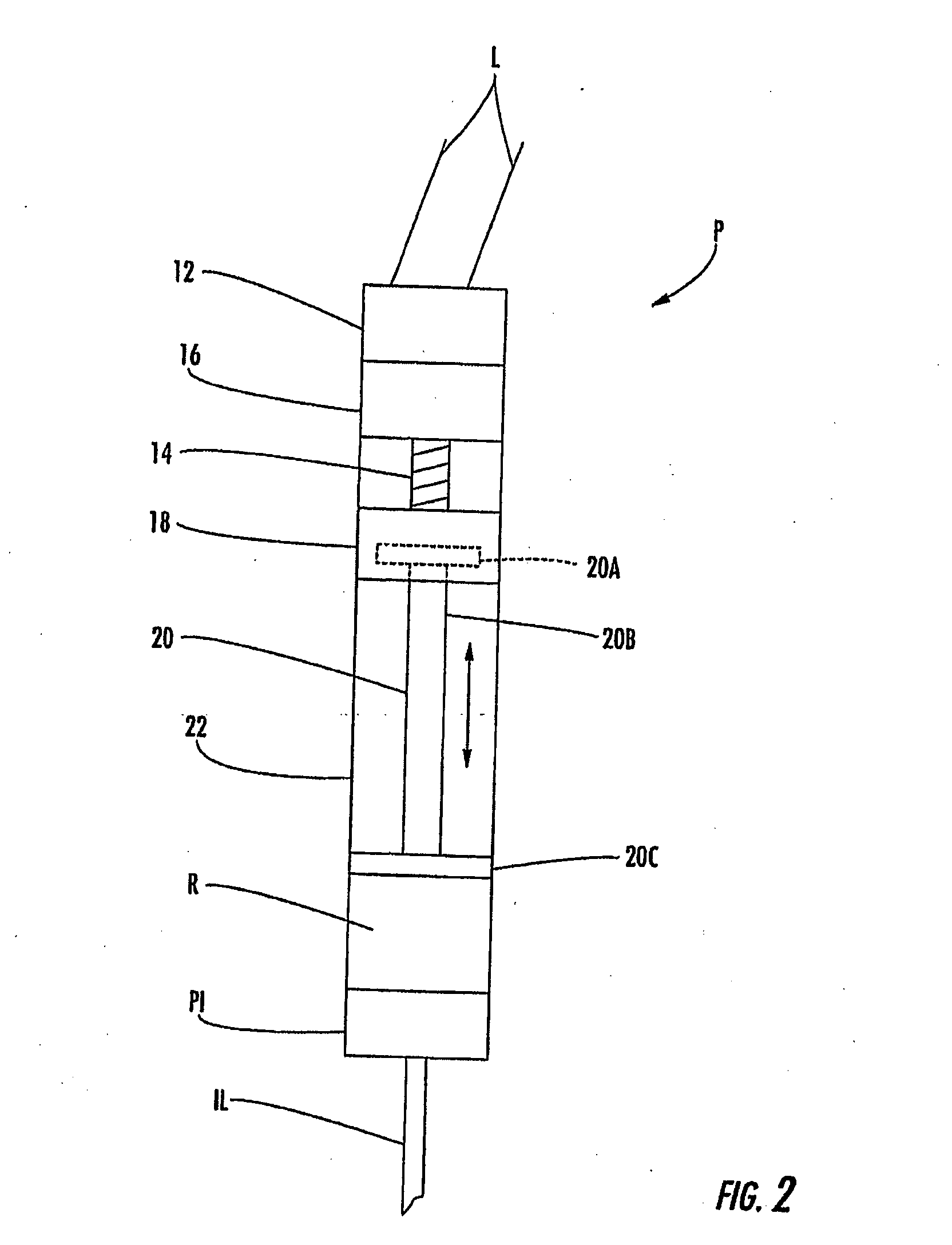
Apparatus and Method for Handling Fluids at Nano-Scale Rates. A linear displacement pump produces non-pulsatile liquid flow rates as low as the nl/mm range. The pump includes a servo motor, a gear reduction, a lead screw, a linear stage, a barrel, and a plunger extending into the barrel and coupled to the stage. A microfluidic interconnect device can be coupled to the barrel. One or more of these pumps can be disposed in a thermally controlled pump assembly that includes a pump housing, a thermally conductive body disposed in the housing and including first and second opposing sides, and a temperature regulating element such as a thermoelectric device disposed in thermal contact with the thermally conductive body on a side thereof opposite to the barrel or barrels of the pumps.

Description


Claims


Application Information

Patent Timeline
Owner SCIEX
Why Eureka
Eureka Blog
Learn More